Home/
Registry/
Ford/
Bronco/
1992-1996/
1993 Ford Bronco/
Photo
supermotors.net/registry/media/261580
1993 Ford Bronco Electronic Shift Transfer Case Wiring Diagram (4x4 E-Shift)
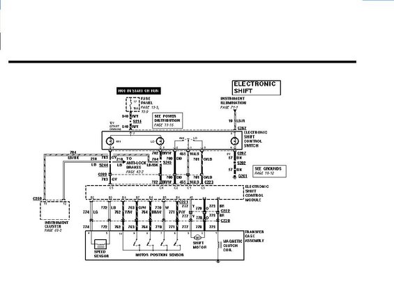
Wiring diagram for the electronic shift transfer-case system showing the shift control module, motor position sensor, and color-coded circuits.
Part of 1992-1996 Ford Bronco Wiring Diagrams
This document is a Ford factory-style wiring diagram for the ELECTRONIC SHIFT transfer case system, uploaded to a 1993 Ford Bronco gallery as "Auto-Tcase.JPG". It shows the complete electric shift-on-the-fly circuit: power feed from fuse panel position 17 (10A, hot in start or run, circuit 640 R/Y through splice S215), the Electronic Shift Control Switch (4X4/LO positions, connector C267) with instrument illumination feed (19 LB/R) and ground path (57 BK through S202 to G201). Wiring runs to the Electronic Shift Control Module via circuits 780 DB, 465 W/LB, 781 O/LB, 782/702 BR/W (connector C223), plus 784 LB/BK and 210 LB/783 GY branches to the instrument cluster (C250) and anti-lock brakes (S244, C209). The module's output side (connectors C220/C221/C222) drives the Transfer Case Assembly, containing the speed sensor (circuits 774 LG, 772 LB), motor position sensor (762, 763 Y/W, 760 O/W, 764 BR/W, 770 W, 771), shift motor (777 P/Y, 778 O), and magnetic clutch coil (779 BR). Cross-references cite Power Distribution (page 13-16), Grounds (page 10-12), Instrument Illumination (page 71-1), Instrument Cluster (page 60-2), Anti-Lock Brakes (page 42-2), and Fuse Panel (pages 13-3, 13-9). A reader can trace wire colors, circuit numbers, connector IDs, and pin locations for diagnosing electric transfer case shift problems.
Is this accurate? Sign in to help verify it.
Frequently asked questions
- What fuse powers the electronic shift transfer case system?
- Power comes from fuse panel position 17, a 10A fuse that is hot in start or run, feeding circuit 640 R/Y through splice S215 to the Electronic Shift Control Switch (see fuse panel pages 13-3 and 13-9).
- What components are inside the transfer case assembly on this diagram?
- The transfer case assembly contains a speed sensor, a motor position sensor, the shift motor, and a magnetic clutch coil.
- What wire circuits connect the shift control switch to the electronic shift control module?
- Circuits 780 DB, 465 W/LB, 781 O/LB, and 782/702 BR/W run from the switch through connector C223 to the module, along with 784 LB/BK and 783 GY/210 LB branches to the instrument cluster and anti-lock brakes.
- How is the electronic shift control switch grounded?
- Through circuit 57 BK from connector C267, via splice S202 to ground G201 (see Grounds, page 10-12).
- Which circuit operates the magnetic clutch coil?
- Circuit 779 BR from the electronic shift control module, through connectors C222 and C220 to pin 1 of the transfer case connector.
Comments
More from this build








No comments yet.