Home/
Registry/
Ford/
Bronco/
1992-1996/
1993 Ford Bronco/
Photo
supermotors.net/registry/media/285563
1993 Ford Bronco Electronic Shift Transfer Case Wiring Diagram (AOD & E4OD)

Reference · 1992-1996 BroncoAll 411 wiring diagrams

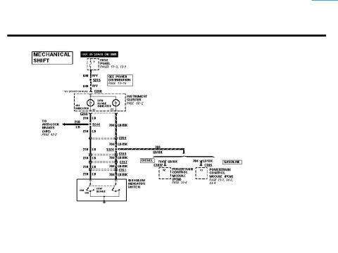
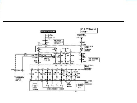

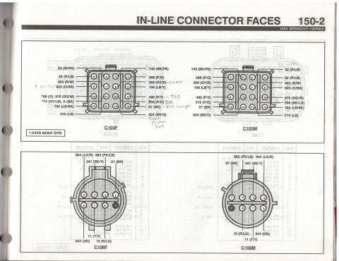
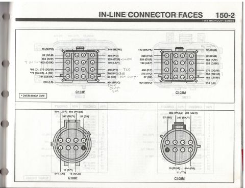
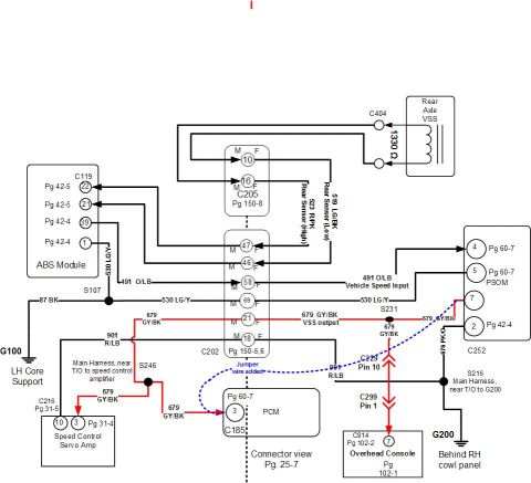






Wiring diagram for the electronic shift control module covering AOD and E4OD transmissions with manual lever position sensor circuits.
Part of 1992-1996 Ford Bronco Wiring Diagrams
This document is a wiring diagram page titled "ELECTRONIC SHIFT," covering the power, ground, and transmission-position-switch circuits for the electronic shift control module (electronic shift transfer case) on a Ford truck/Bronco. Power is supplied two ways: a Hot At All Times feed through fuse panel position 12 with a 24A circuit breaker (circuit 171/517 BK/W through splice S237 and connectors C209 and C222 to module pin A6), and a Hot In Run feed through fuse position 14 with a 10A fuse (circuit 296 W/P through splice S242, C209 and C222 to module pin A7). Module pin B1 feeds circuit 463 R/W through C221, C209, and C202, branching to either the AOD transmission's Park/Neutral Position Switch (via C103 and C167) or the E4OD transmission's Manual Lever Position (MLP) sensor (via C103 and C1012), which grounds through circuit 57 BK at G100. Module grounds are at pin A2 (circuit 57 BK through splice S203 to G201) and pin A3 (circuit 570 BK/W through C222, C209, and splice S216 to G200). Cross-references point to power distribution pages 13-13/13-15, grounds pages 10-4/10-10/10-13, and switch testing pages 149-10/149-11.
Is this accurate? Sign in to help verify it.
Frequently asked questions
- What fuses power the electronic shift control module?
- Two feeds: fuse panel position 12, a 24A circuit breaker that is Hot At All Times (circuit 171/517 BK/W to module pin A6), and fuse position 14, a 10A fuse that is Hot In Run (circuit 296 W/P to module pin A7).
- Where does the electronic shift control module ground?
- Module pin A2 grounds through circuit 57 BK via splice S203 to ground G201, and pin A3 grounds through circuit 570 BK/W via C222, C209, and splice S216 to ground G200. The MLP sensor grounds through 57 BK at G100.
- What wire circuit connects the module to the transmission position switch?
- Circuit 463 R/W runs from module pin B1 through connectors C221, C209, and C202, then via C103 to either the AOD Park/Neutral Position Switch (through C167) or the E4OD Manual Lever Position (MLP) sensor (through C1012).
- Does this diagram cover both AOD and E4OD transmissions?
- Yes. It shows separate branches: the AOD transmission uses a Park/Neutral Position Switch (testing on page 149-11), while the E4OD uses a Manual Lever Position (MLP) sensor (testing on page 149-10).
- Where can I find the ground and power distribution details referenced here?
- Power distribution is on pages 13-13 and 13-15; grounds are shown on page 10-4 (G100), page 10-13 (G201), and page 10-10 (G200).






No comments yet.