Home/
Registry/
Ford/
Bronco/
1992-1996/
1993 Ford Bronco/
Photo
supermotors.net/registry/media/291864
Electric Fan Wiring Diagram - Dual Relay, Temp Switch & Manual Switch (Bronco)
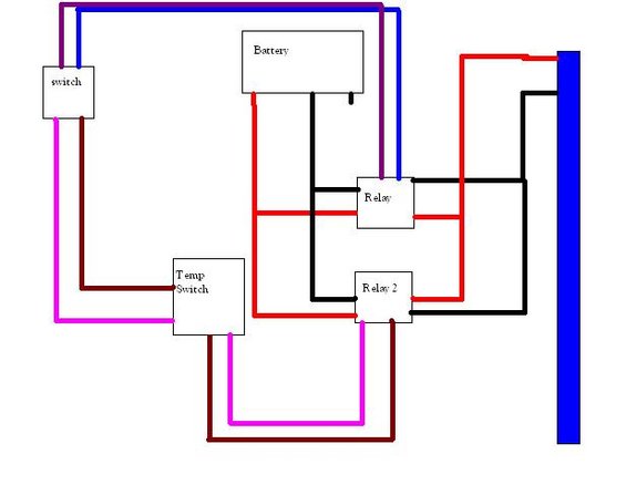
Wiring diagram showing a battery, switch, temperature switch, and two relays connected with color-coded wires to a load.
This document is a simple, hand-made (drawn in a basic graphics program) wiring diagram, uploaded as "Fan.JPG" to a 1993 Ford Bronco gallery, apparently illustrating an electric fan wiring setup. It contains five labeled components: a manual "switch," a "Battery," two relays ("Relay" and "Relay 2"), and a "Temp Switch." Colored lines (red, black, blue, purple, magenta/pink, and dark maroon) connect these components to a large unlabeled blue vertical bar on the right edge of the image, which likely represents the electric fan or its motor. The diagram conveys the general concept: battery power routes through the two relays, which are triggered either by the manual switch or by the temperature switch, allowing automatic and manual control of the fan. However, the document contains no wire gauges, fuse or amperage ratings, relay terminal/pin numbers, part numbers, or any vehicle-specific text. It is undated and does not state applicability to any specific make, model, or year. A reader can learn the basic component layout and rough connection topology for a dual-relay electric fan circuit with both manual and thermostatic switching, but would need additional information (relay pinouts, fusing) to actually build the circuit safely.
Is this accurate? Sign in to help verify it.
Frequently asked questions
- What components are shown in this electric fan wiring diagram?
- Five labeled components: a manual switch, a battery, two relays (labeled 'Relay' and 'Relay 2'), and a temp switch, all connected by colored wires to a large blue bar presumed to be the fan.
- How many relays does this fan wiring setup use?
- Two relays are shown, labeled 'Relay' and 'Relay 2'.
- Does the diagram show both manual and automatic fan control?
- Yes: it includes both a manual 'switch' and a 'Temp Switch', each wired to the relays, suggesting the fan can be triggered manually or by temperature.
- Does this diagram specify fuse sizes, wire gauges, or relay pin numbers?
- No. The diagram contains only component labels and colored connecting lines; no fuse ratings, wire gauges, pin numbers, or part numbers are given.
Comments
More from this build








No comments yet.