1978 Ford Bronco Engine Bay Component Location Diagram - I-6, V-6, V-8

Reference · 1978-1979 BroncoAll 48 service procedures
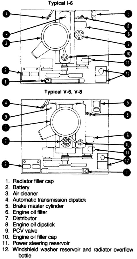

Underhood component-location diagrams for inline-six and V-6/V-8 engines with a numbered legend of fluid reservoirs and service points.
Part of 1978-1979 Ford Bronco Service Procedures
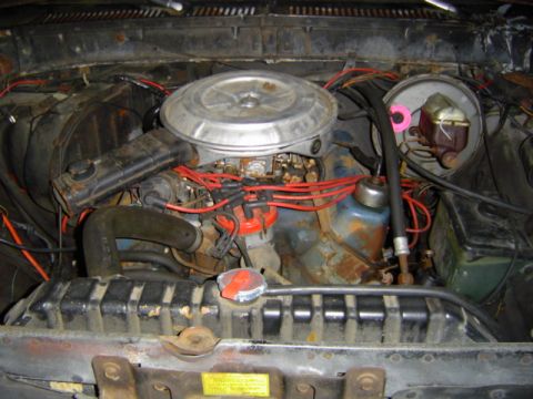
This document is an engine compartment (engine bay) component location diagram showing two overhead-view illustrations: one labeled 'Typical I-6' for inline six-cylinder engines and one labeled 'Typical V-6, V-8' for V6 and V8 engines. Each illustration uses numbered callouts (1 through 12) pointing to the locations of key underhood service items. The shared legend identifies: 1. Radiator filler cap, 2. Battery, 3. Air cleaner, 4. Automatic transmission dipstick, 5. Brake master cylinder, 6. Engine oil filter, 7. Distributor, 8. Engine oil dipstick, 9. PCV valve, 10. Engine oil filler cap, 11. Power steering reservoir, and 12. Windshield washer reservoir and radiator overflow bottle. A reader can use this page to locate routine maintenance points in the engine compartment, fluid fill and check locations (oil, transmission, brake, power steering, washer/coolant overflow), filter locations, and ignition components, for either engine layout. The document itself contains no year, make, model, part numbers, or torque specifications; it was uploaded to a 1978 Ford Bronco gallery and is consistent with a general service-manual underhood orientation page.
Is this accurate? Sign in to help verify it.
Frequently asked questions
- Where is the PCV valve shown in the diagram?
- The PCV valve is callout number 9, located near the top of the engine adjacent to the air cleaner in both the I-6 and V-6/V-8 diagrams.
- What underhood components does this diagram identify?
- Twelve items: radiator filler cap, battery, air cleaner, automatic transmission dipstick, brake master cylinder, engine oil filter, distributor, engine oil dipstick, PCV valve, engine oil filler cap, power steering reservoir, and the windshield washer reservoir/radiator overflow bottle.
- Does the diagram cover different engine types?
- Yes, it includes two layouts: one labeled 'Typical I-6' for inline six engines and one labeled 'Typical V-6, V-8' for V6 and V8 engines.
- Which callout number is the brake master cylinder?
- The brake master cylinder is callout number 5, shown on the driver-side firewall area in both diagrams.
- Where is the windshield washer reservoir located per this diagram?
- Callout 12 shows the windshield washer reservoir and radiator overflow bottle located together on one side of the engine compartment near the radiator area.
No comments yet.