Home/
Registry/
Ford/
Bronco/
1978-1979/
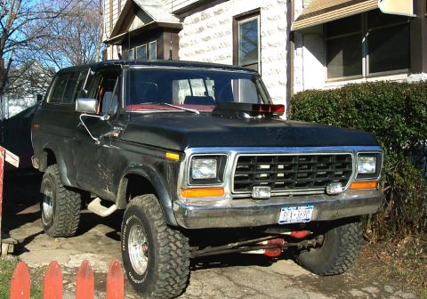
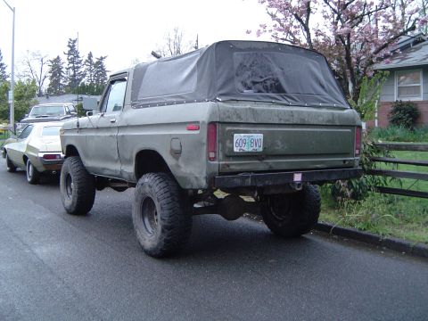
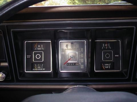
1979 Ford Bronco/
Photo
supermotors.net/registry/media/1032658
1979 Ford Bronco/F100-F350 Heater & A/C System Component Location Diagram

Reference · 1978-1979 BroncoAll 48 service procedures
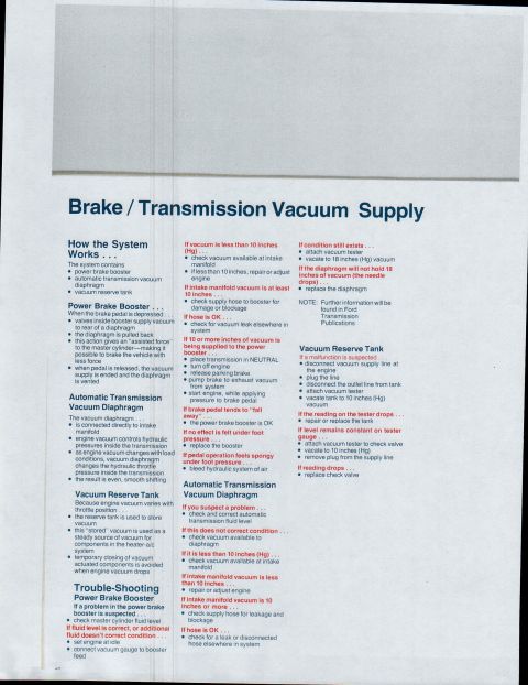
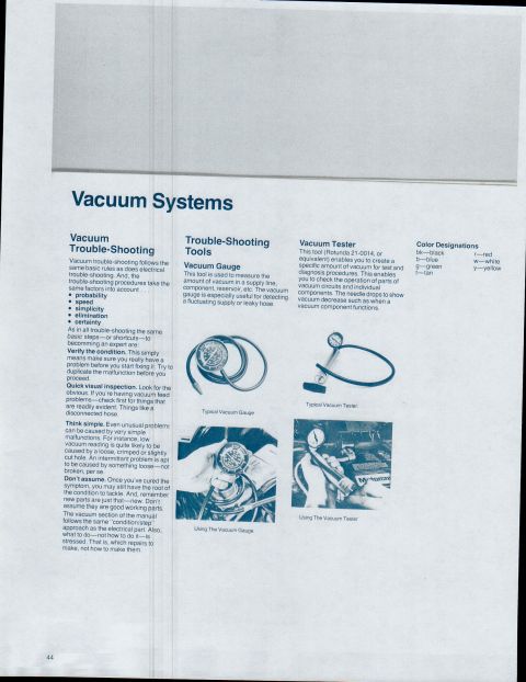
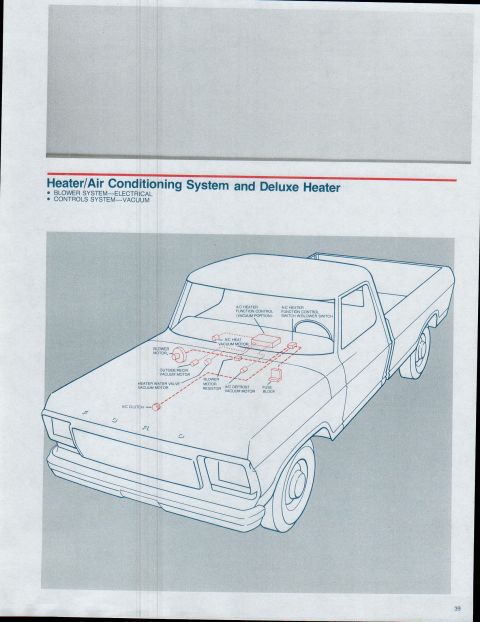
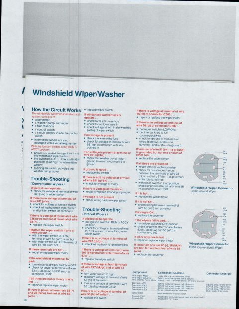


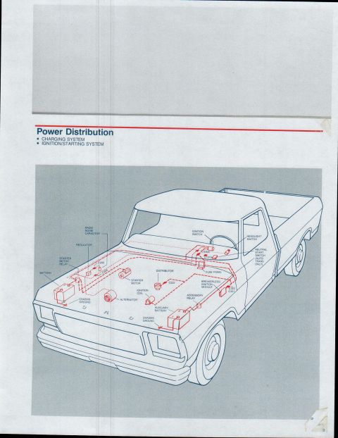
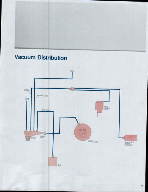
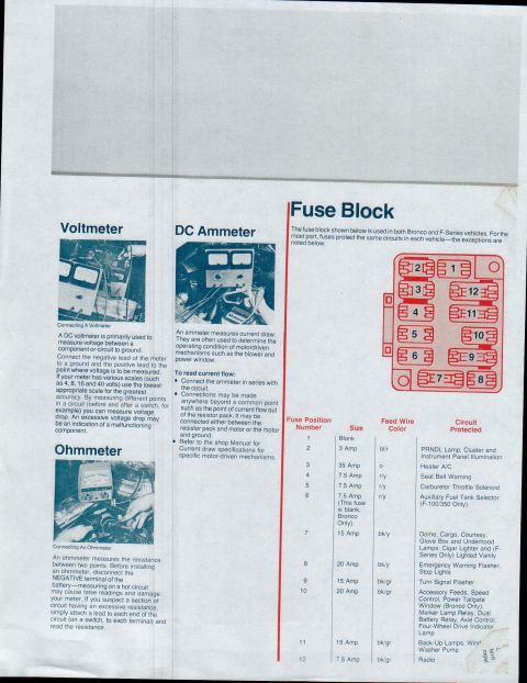
Cutaway locator for heater/AC and deluxe heater: blower motor, A/C heat function and selector controls, vacuum motors (outside-recirc, water valve, defrost), A/C clutch, and fuse block.
Part of 1978-1979 Ford Bronco Service Procedures
This page (page 39) is from a Ford truck electrical/vacuum reference covering the Heater/Air Conditioning System and Deluxe Heater. It addresses two subsystems: the blower system (electrical) and the controls system (vacuum). The page consists of an isometric line drawing of a Ford pickup truck with the HVAC components drawn in red at their approximate installed locations, connected by dashed lines representing vacuum/electrical routing. Labeled components include the A/C heater function control (vacuum portion), the A/C heater function control switch with blower switch, the A/C heat vacuum motor, the blower motor, the outside/recirculate vacuum motor, the heater water valve vacuum motor, the blower motor resistor, the A/C defrost vacuum motor, the fuse block, and the A/C clutch. From this diagram a reader can learn where each heater/air-conditioning electrical and vacuum component is located in the vehicle, most components cluster on or behind the firewall and dash area, with the A/C clutch at the front of the engine compartment. The page is a component-location overview rather than a wiring schematic; no wire colors, fuse ratings, or part numbers are shown. It belongs to a multi-page set uploaded as "1979 Bronco F100 through F350."
Is this accurate? Sign in to help verify it.
Frequently asked questions
- What components are shown in the 1979 Ford truck heater/A/C system diagram?
- The diagram labels the A/C heater function control (vacuum portion), A/C heater function control switch with blower switch, A/C heat vacuum motor, blower motor, outside/recirculate vacuum motor, heater water valve vacuum motor, blower motor resistor, A/C defrost vacuum motor, fuse block, and A/C clutch.
- What two subsystems does this heater/air conditioning page cover?
- It covers the blower system (electrical) and the controls system (vacuum), for the heater/air conditioning system and deluxe heater.
- Where is the blower motor resistor located according to the diagram?
- The blower motor resistor is shown on the firewall/cowl area near the blower motor and vacuum motors, behind the engine compartment on the passenger-side dash region.
- Are the heater controls on this truck vacuum operated?
- Yes: the controls system is identified as vacuum, and the diagram shows several vacuum motors (A/C heat, outside/recirculate, heater water valve, and A/C defrost vacuum motors) plus the vacuum portion of the A/C heater function control.
No comments yet.