Home/
Registry/
Suzuki/
Samurai/
1986-1995/
“Little Blue”/
Photo
supermotors.net/registry/media/420640
Suzuki Cigarette Lighter & Illumination Wiring Diagram - Fuse, Wire Colors
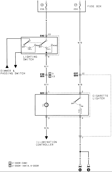
Factory wiring diagram routing the fuse box to the lighting switch, cigarette lighter and illumination controller with wire color codes.
This document is a wiring diagram covering the cigarette lighter and instrument illumination feed circuit. Power originates at the fuse box: fuse 13 (15A) feeds a White (W) wire to connector E40 pin 10 at the lighting switch (positions OFF/TAIL/HEAD), which also connects to the dimmer & passing switch. From the lighting switch, a Red/Yellow (R/Y) wire runs through connector E38/G05 (pin 3 on 2-door CAMI-built vehicles, pin 13 on 2-door Iwata-built and 4-door vehicles) to connector G20 pin 1, powering the cigarette lighter's illumination bulb, then exits on a Red/Green (R/G) wire to the illumination controller. Fuse 17 (20A) feeds a White/Black (W/B) wire through connector E37/G08 pin 12 to the lighter's heating element (OFF/ON), with Black (B) ground wires returning to chassis ground points 10 and 9. The diagram gives connector IDs, pin numbers, wire color codes, and fuse amperages, letting a reader trace and troubleshoot both the lighter power circuit and its illumination circuit.
Is this accurate? Sign in to help verify it.
Frequently asked questions
- What fuse powers the cigarette lighter in this diagram?
- Fuse 17, a 20A fuse in the fuse box, feeds the cigarette lighter heating element via a White/Black (W/B) wire through connector E37/G08 pin 12.
- What fuse and wire feed the lighter's illumination bulb?
- Fuse 13 (15A) feeds a White (W) wire to the lighting switch (E40 pin 10); with the switch in TAIL or HEAD, power flows on a Red/Yellow (R/Y) wire through E38/G05 to G20 pin 1 for the illumination bulb, exiting on Red/Green (R/G) to the illumination controller.
- Where does the cigarette lighter circuit ground?
- Black (B) wires run from the lighter (pins 4 and 7 area) to chassis ground points labeled 10 and 9.
- Do connector pins differ by body style?
- Yes. At connector E38/G05, pin 3 applies to 2-door CAMI-built vehicles and pin 13 applies to 2-door Iwata-built and 4-door vehicles, per the legend.
- What are the lighting switch positions shown?
- The lighting switch has OFF, TAIL, and HEAD positions, and connects to the dimmer & passing switch.
Comments
More from this build














No comments yet.