Home/
Registry/
Suzuki/
Samurai/
1986-1995/
“Little Blue”/
Photo
supermotors.net/registry/media/420636
Suzuki Samurai Stop/Brake Light Wiring Diagram - Switch, Fuse & Connectors
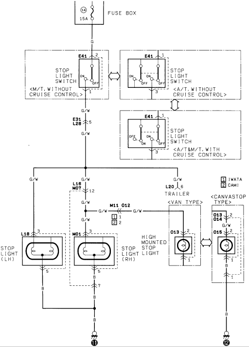
Factory stop-light wiring diagram showing stop-light switch variants, left/right stop lights and the high-mounted stop lamp with wire color codes.
Part of 1986-1995 Suzuki Samurai Wiring Diagrams
This document is a stop light (brake light) wiring diagram, apparently from a Suzuki factory service manual. Power originates at fuse 14, a 15A fuse in the fuse box, feeding a green (G) wire to the stop light switch (connector E41). Three switch variants are shown: manual transmission without cruise control, automatic transmission without cruise control, and A/T & M/T with cruise control, each with its own pinout and ON/OFF contact arrangement. From the switch, a green/white (G/W) wire passes through connector E31/L28 (pin 5) and branches to the left stop light (connector L18), right stop light (connector M01), a trailer connector (L20 pin 6), and a high mounted stop light. Two high-mount stop light configurations are diagrammed: a van type (connector O13) and a canvas top type (connectors O13/O14 and O15). A legend distinguishes IWATA (1) and CAMI (2) production plants at connector M11/O12. All lamps ground through black (B) wires to ground points 11 and 12. Readers can learn the fuse rating, wire colors, connector IDs and pin numbers, and switch variations for diagnosing brake light problems.
Is this accurate? Sign in to help verify it.
Frequently asked questions
- What fuse powers the Suzuki Samurai brake lights?
- Fuse 14 in the fuse box, rated 15A, supplies the stop light circuit via a green (G) wire.
- What wire colors are used in the stop light circuit?
- Green (G) from the fuse to the stop light switch, green/white (G/W) from the switch to the stop lights, trailer, and high mounted stop light, and black (B) for the grounds.
- Are there different stop light switch configurations?
- Yes, three variants of switch E41 are shown: M/T without cruise control, A/T without cruise control, and A/T & M/T with cruise control, each with different pin arrangements.
- Does the diagram cover a high mounted (third) brake light?
- Yes. It shows a van type version using connector O13 and a canvas top type version using connectors O13/O14 and O15.
- What connectors are used for the left and right stop lights?
- The left stop light uses connector L18 (pins 3 and 5) and the right stop light uses connector M01 (pins 3, 5, and 7); both ground through black wires to ground point 11.
Comments
More from this build














No comments yet.