Home/
Registry/
Suzuki/
Samurai/
1986-1995/
“Little Blue”/
Photo
supermotors.net/registry/media/420637
Suzuki Samurai Back-Up Light Wiring Diagram - Reverse Light Switch Circuit
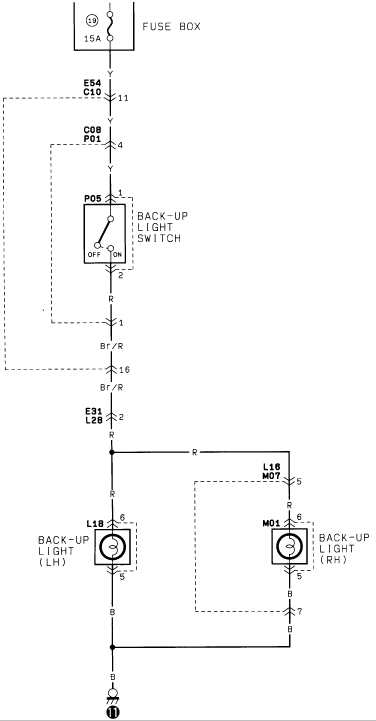
Factory back-up light wiring diagram from the fuse box through the back-up light switch to the left and right reverse lamps with wire codes.
Part of 1986-1995 Suzuki Samurai Wiring Diagrams
This document is a single-page wiring diagram for the back-up (reverse) light circuit, uploaded to a 1986 Suzuki Samurai gallery. Power originates at the fuse box through fuse position 19, a 15A fuse, on a Yellow (Y) wire. The circuit passes through connectors E54/C10 (pin 11) and C08/P01 (pin 4) to the back-up light switch (connector P05, pins 1 and 2), which is shown with OFF/ON positions. From the switch, the wire changes to Red (R), then Brown/Red (Br/R) through pins 1 and 16, then back to Red through connector E31/L28 (pin 2). The Red wire splits at a junction: one branch feeds the left-hand back-up light (connector L18, pins 6 and 5), and the other passes through connector L16/M07 (pin 5) to the right-hand back-up light (connector M01, pins 6, 5, and 7). Both lamps ground through Black (B) wires that join and terminate at a chassis ground. A reader can learn the fuse rating, connector identifiers, pin numbers, and wire colors needed to diagnose non-working reverse lights on this vehicle.
Is this accurate? Sign in to help verify it.
Frequently asked questions
- What fuse powers the back-up lights in this diagram?
- Fuse position 19 in the fuse box, rated at 15A.
- What wire colors are used in the back-up light circuit?
- Yellow (Y) from the fuse box to the back-up light switch, Red (R) and Brown/Red (Br/R) between the switch and the lamps, and Black (B) for the ground side of both lamps.
- Which connectors are in the back-up light circuit?
- E54/C10 (pin 11), C08/P01 (pin 4), P05 (back-up light switch, pins 1 and 2), E31/L28 (pin 2), L18 (LH lamp, pins 6 and 5), L16/M07 (pin 5), and M01 (RH lamp, pins 6, 5, and 7).
- How do the back-up lamps get ground?
- Both the LH and RH back-up lights ground through Black (B) wires that join together and run to a single chassis ground point.
- How does power reach the right-hand back-up light?
- After connector E31/L28, the Red wire splits at a junction; one branch goes through connector L16/M07 pin 5 to the RH back-up light at connector M01 pin 6.
Comments
More from this build














No comments yet.