Home/
Registry/
Suzuki/
Samurai/
1986-1995/
“Little Blue”/
Photo
supermotors.net/registry/media/420635
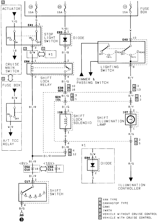
Suzuki Samurai A/T Shift Lock & Shift Switch Wiring Diagram - Solenoid, Relay
Reference · 1986-1995 SamuraiAll 73 wiring diagrams



Factory wiring diagram of the shift-lock relay and solenoid, stop-light switch, lighting switch and shift illumination circuits with connector codes.
Part of 1986-1995 Suzuki Samurai Wiring Diagrams
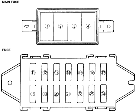
This document is one page of an automatic transmission wiring diagram (page 2, per the filename Atranny2.gif) covering the shift lock and shift switch circuitry. It shows three 15A fuses in the fuse box (positions 14, 20, and 13) feeding the stop light switch, a diode (E83), the shift lock relay (E64), the lighting switch (E40) with dimmer & passing switch, the shift lock solenoid (I06), the shift illumination lamp (I07), and the shift switch (C17) with gear-position contacts. It also depicts the cruise main switch/actuator (E41) branch for vehicles with cruise control and the A/T TCC relay branch for vehicles without cruise control. Wire colors are labeled throughout, including Y/G, Lg, G/W, Y/Bl, Bl/B, Bl/G, Bl/R, B/W, W/R, R/Y, R/G, B/G, W, and G. Connector references include E38/G05, G24/I01, E54/C10 (<8V>), E55/C11 (<16V>), and E84 (a second diode, noted *1). A legend distinguishes van type, canvastop type, CAMI-built, and IWATA-built vehicles, plus vehicles with and without cruise control. Output R/G goes to the illumination controller. Readers can trace fuse feeds, wire colors, and connector pins for diagnosing shift lock or shift illumination problems.
Is this accurate? Sign in to help verify it.
Frequently asked questions
- What fuses feed the shift lock and lighting circuits in this diagram?
- Three 15A fuses in the fuse box: positions (14), (20), and (13).
- What wire colors connect to the shift lock solenoid (I06)?
- The shift lock solenoid receives Bl/G (blue/green) on pin 1 and outputs B (black) on pin 2.
- What components are shown in the shift lock circuit?
- The stop light switch, diode E83, shift lock relay E64, shift lock solenoid I06, shift switch C17, shift illumination lamp I07, lighting switch E40 with dimmer & passing switch, plus diode E84 (*1).
- What do the numbered legend symbols mean?
- [1] Van type, [2] Canvastop type, [3] CAMI, [4] IWATA, [5] Vehicle without cruise control, [6] Vehicle with cruise control.
- Where does the R/G wire from the shift illumination lamp go?
- The R/G (red/green) wire runs from the shift illumination lamp to the illumination controller.

No comments yet.