Home/
Registry/
Suzuki/
Samurai/
1986-1995/
“Little Blue”/
Photo
supermotors.net/registry/media/420639
Suzuki Samurai/Sidekick Charging System Wiring Diagram - Generator & IC Regulator
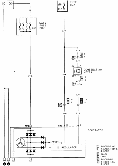
Factory charging-circuit wiring diagram routing the 60A main fuse box and 15A fuse through the combination meter to the generator and IC regulator, with 2-door/4-door CAMI and IWATA alternator variants.
Part of 1986-1995 Suzuki Samurai Wiring Diagrams
This document is a charging system wiring diagram showing the generator (alternator) circuit for a Suzuki vehicle. It traces power from the battery through a 60A main fuse box directly to the generator output (wire color W/G, connector A02), and a second path through fuse position 18 (15A) in the fuse box on a B/W wire that feeds the charge (CHG) indicator lamp in the combination meter. From the meter, a W/R wire returns to the generator's IC regulator via connectors G06/E37 (pin 18) and E54/C10, terminating at generator connector C02 (pins 3 and 2). Intermediate connectors E38/G05, G11 (pin 9), and G09 are shown with pin numbers that vary by body/engine variant. The generator internals are depicted schematically: three-phase stator windings, rectifier diode bridge, field coil, capacitor, and the IC regulator. A legend keys numbered boxes to vehicle variants: 2-DOOR·CAMI, 2-DOOR·IWATA/4-DOOR, IWATA, CAMI, 2-DOOR·8V, and 2-DOOR·16V/4-DOOR, indicating the diagram covers multiple production plants (CAMI, Iwata) and 8-valve/16-valve engines. Wire colors used are B, B/W, W/G, and W/R. Ground points are marked with symbols 7 and 2.
Is this accurate? Sign in to help verify it.
Frequently asked questions
- What size fuse protects the charge indicator lamp circuit?
- Fuse position 18 in the fuse box, rated 15A, feeds the B/W wire to the CHG lamp in the combination meter.
- What is the main fuse rating for the generator output circuit?
- The main fuse box contains a 60A fuse in the battery-to-generator circuit.
- What wire colors are used in the charging circuit?
- B (battery), B/W from fuse 18 to the CHG lamp and regulator, W/G from the main fuse box to the generator output (A02), and W/R from the combination meter back to the IC regulator.
- Which connector pins go to the generator's IC regulator?
- Connector C02 pins 3 (B/W) and 2 (W/R) connect to the IC regulator; the main output is at terminal A02 on the W/G wire.
- What do the numbered boxes in the legend mean?
- They indicate variant-specific pin numbers: [1] 2-DOOR·CAMI, [2] 2-DOOR·IWATA/4-DOOR, [3] IWATA, [4] CAMI, [5] 2-DOOR·8V, [6] 2-DOOR·16V/4-DOOR.
Comments
More from this build














No comments yet.