Home/
Registry/
Suzuki/
Samurai/
1986-1995/
“Little Blue”/
Photo
supermotors.net/registry/media/420655
Suzuki EFI Wiring Diagram - ECM, TPS, Injectors, IAC Valve & Temp Sensors
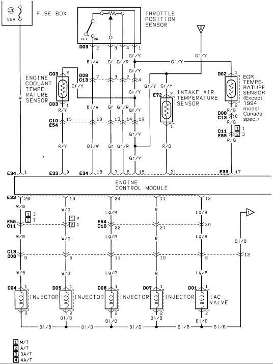
Wiring diagram of engine sensors and fuel injectors connected to the engine control module, including throttle position and temperature sensors.
This document is one page (EFI3) of a multi-page electronic fuel injection (EFI) wiring diagram set, scanned from a Suzuki service manual. It shows the Engine Control Module (ECM) wiring for key EFI sensors and actuators: the Throttle Position Sensor (connector D03), Engine Coolant Temperature Sensor (C03), Intake Air Temperature Sensor (E72), and EGR Temperature Sensor (D02, noted as 'Except 1994 model Canada spec.'), all fed through a 15A fuse (position 13) in the fuse box. The lower half of the diagram shows the ECM outputs to four fuel injectors (connectors D04, D05, D06, D07) and the IAC (Idle Air Control) valve (D01), all sharing a common Bl/B (black/blue) return wire. Wire colors are labeled throughout (Bl/W, Gr, Gr/R, Gr/Y, R/Y, R/B, R/G, W/B, W/G, W, Lg/R, R, Lg/B, Bl/R, Bl/B), along with ECM pin numbers on connectors E33 and E34 and intermediate harness connectors C10/E54, C11/E55, and C13/D08. A legend distinguishes wiring variations by transmission: M/T, A/T, 3A/T, and 4A/T. Useful for tracing sensor circuits, verifying ECM pinouts, and diagnosing injector or IAC valve wiring faults.
This document covers 1994, which may differ from this 1986 Suzuki Samurai.
Is this accurate? Sign in to help verify it.
Frequently asked questions
- What fuse and amperage feeds this EFI circuit?
- The diagram shows the circuit fed from fuse position 13 in the fuse box, rated 15A.
- Which sensors are shown on this EFI wiring diagram?
- The Throttle Position Sensor (connector D03), Engine Coolant Temperature Sensor (C03), Intake Air Temperature Sensor (E72), and EGR Temperature Sensor (D02, except 1994 model Canada spec.).
- What are the injector connector numbers and wire colors?
- The four injectors use connectors D04 (W/B), D05 (W), D06 (Lg/R), and D07 (R), each returning through a common Bl/B (black/blue) wire.
- What wire color goes to the IAC valve?
- The IAC valve (connector D01) is fed by an Lg/B wire from ECM connector E33 pin 12, with a Bl/B return wire.
- What do the numbered legend boxes 1-4 mean?
- They indicate transmission-specific wiring: 1 = M/T, 2 = A/T, 3 = 3A/T, 4 = 4A/T.
Comments
More from this build














No comments yet.