Home/
Registry/
Suzuki/
Samurai/
1986-1995/
“Little Blue”/
Photo
supermotors.net/registry/media/420656
Suzuki EFI Wiring Diagram - ECM, TPS, Injectors, IAC Valve & Temp Sensors
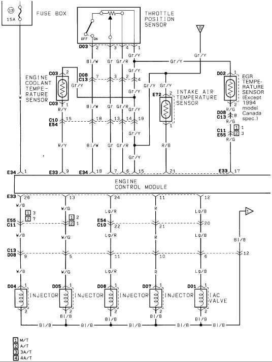
Wiring diagram of engine sensors and fuel injectors connected to the engine control module, including throttle position and temperature sensors.
This is a scanned EFI (electronic fuel injection) wiring diagram page, part of a multi-page set (EFI3.gif), uploaded to a 1986 Suzuki Samurai gallery. It shows the sensor and actuator wiring for the engine control module (ECM). Circuits depicted include: a 15A fuse (position 13) feeding the throttle position sensor (connector D03, pins 1-4, wires Bl/W, Gr, Gr/R, Gr/Y); the engine coolant temperature sensor (connector C03, wire R/Y); the intake air temperature sensor (connector E72, wires Gr/Y and R/B); and the EGR temperature sensor (connector D02, wires Gr/Y and R/G) noted as 'Except 1994 model Canada spec.' These sensor circuits enter the ECM at connectors E33/E34 (pins 1, 6, 7, 9, 15, 17, 18, 21). Output circuits from the ECM (pins 11, 12, 13, 24, 26) drive four fuel injectors (connectors D04, D05, D06, D07) and the IAC (idle air control) valve (D01) via wires W/B, W/G, Lg/R, R, and Lg/B, all grounded through Bl/B wiring. Intermediate connectors C10/E54, C11/E55, and C13/D08 are shown with pin numbers. A legend distinguishes M/T, A/T, 3A/T, and 4A/T transmission variants.
Is this accurate? Sign in to help verify it.
Frequently asked questions
- What wire colors connect the throttle position sensor to the ECM?
- The throttle position sensor (connector D03, pins 2, 3, 4, 1) uses Bl/W, Gr, Gr/R, and Gr/Y wires, which route through intermediate connectors to the engine control module.
- What connector and wires does the intake air temperature sensor use?
- The intake air temperature sensor uses connector E72; pin 2 is a Gr/Y wire and pin 1 is an R/B wire going to the ECM.
- What fuse feeds this EFI sensor circuit?
- A 15A fuse in fuse box position (13) supplies the circuit at the top of the diagram.
- How are the fuel injectors and IAC valve wired?
- Four injectors (connectors D04, D05, D06, D07) and the IAC valve (D01) are driven from ECM pins 26, 13, 24, 11, and 12 via W/B, W/G, Lg/R, R, and Lg/B wires, with Bl/B ground wiring on pin 2 of each device.
- Does the EGR temperature sensor circuit apply to all models?
- No — the EGR temperature sensor (connector D02, wires Gr/Y and R/G) is noted as applying 'Except 1994 model Canada spec.'
Comments
More from this build














No comments yet.