Home/
Registry/
Suzuki/
Samurai/
1986-1995/
“Little Blue”/
Photo
supermotors.net/registry/media/420665
Suzuki Turn Signal & Hazard Warning Wiring Diagram - Flasher Relay Circuit
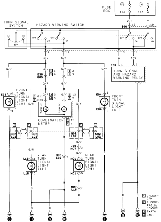
Wiring diagram of the turn signal and hazard warning system showing the switches, relay and front and rear turn signal lights.
Part of 1986-1995 Suzuki Samurai Wiring Diagrams
This document is a wiring diagram for the turn signal and hazard warning light circuit. Power originates at the fuse box through fuse 15 (15A) and fuse 19 (15A), feeding via W/G and Y wires through connector E40 (pins 18 and 19) to the hazard warning switch and turn signal switch. A turn signal and hazard warning relay (connector E59) controls the flasher function. The G/R (left) and G/Y (right) circuits branch through connectors E38/G05 to the front turn signal lights (E27 LH, E04 RH), the combination meter turn indicators (TURN LH / TURN RH via connectors G11/G09), and through body connectors G02/L02 to the rear turn signal lights (L18 LH via G/R, M01 RH via G/Y, with intermediate connectors L16/M07 and G06/E37). All lamps return to ground on black (B) wires at numbered chassis ground points (1, 6, 9, 10, 11). A legend distinguishes connector pinouts by build variant: [1] 2-door CAMI, [2] 2-door IWATA and 4-door, [3] IWATA, [4] CAMI, indicating the diagram covers vehicles from both the CAMI and IWATA assembly plants in 2-door and 4-door configurations.
Is this accurate? Sign in to help verify it.
Frequently asked questions
- What fuses power the turn signal and hazard circuit?
- Two 15A fuses in the fuse box, positions 15 and 19, feed the circuit through W/G and Y wires via connector E40 pins 18 and 19.
- What wire colors are used for left and right turn signals?
- G/R (green/red) is the left turn signal circuit and G/Y (green/yellow) is the right turn signal circuit; grounds are B (black).
- What connectors are used for the front and rear turn signal lights?
- Front: E27 (LH) and E04 (RH), each with signal on pin 2 and ground on pin 1. Rear: L18 (LH) and M01 (RH), with signal on pin 3 and ground on pin 5.
- What does the flasher relay connect to?
- The turn signal and hazard warning relay connects through connector E59: pin 1 gets G from the switch, pin 3 gets Y/W, and pin 2 goes to ground (B).
- What do the legend numbers [1]-[4] mean on the diagram?
- They indicate build-variant-specific pinouts: [1] 2-door CAMI, [2] 2-door IWATA and 4-door, [3] IWATA, [4] CAMI.
Comments
More from this build














No comments yet.