Home/
Registry/
Suzuki/
Samurai/
1986-1995/
“Little Blue”/
Photo
supermotors.net/registry/media/420670
Suzuki HVAC Wiring Diagram - Blower Motor, Blower Switch & A/C Circuit
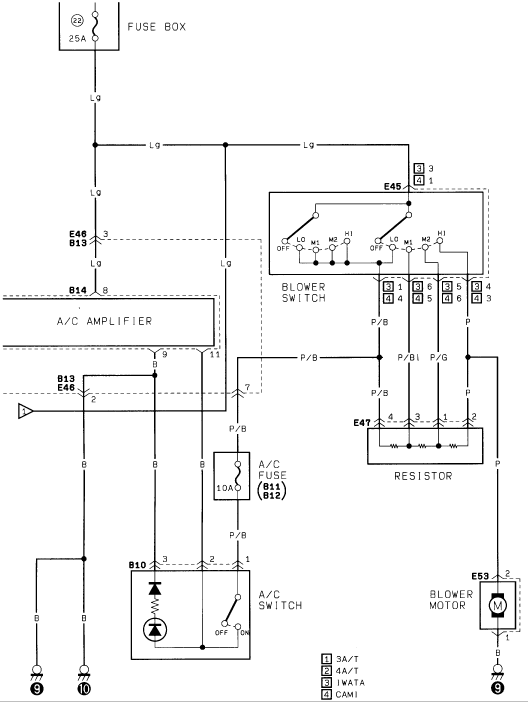
Wiring diagram of the A/C blower system showing the blower switch, resistor, A/C switch and blower motor.
Part of 1986-1995 Suzuki Samurai Wiring Diagrams
This document is a factory-style HVAC wiring diagram (page 2 of a multi-page HVAC set) showing the blower motor and A/C control circuit for a Suzuki vehicle. Power originates at fuse 23 (25A) in the fuse box and travels on a light green (Lg) wire through connectors E46/B13 and B14 to the A/C amplifier, and also to the E45 blower switch. The blower switch has OFF, LO, M1, M2, and HI positions and feeds the E47 blower resistor block via P/B, P/Bl, and P/G wires, with the P wire continuing to the E53 blower motor, which grounds through a black (B) wire at ground point 9. A separate branch runs through a 10A A/C fuse (connectors B11/B12) on a P/B wire to the B10 A/C switch (with OFF/ON positions, an internal diode, and indicator lamp), which grounds at points 9 and 10. Connector pin numbers are shown throughout, with a legend indicating variant-specific pinouts: [1] 3A/T, [2] 4A/T, [3] IWATA-built, [4] CAMI-built vehicles. Readers can trace blower speed circuits, identify wire colors and connector/pin assignments, and locate the A/C fuse and amplifier in the circuit.
Is this accurate? Sign in to help verify it.
Frequently asked questions
- What fuse powers the blower/A/C circuit in this diagram?
- Fuse 23, rated 25A, in the fuse box supplies the circuit on a light green (Lg) wire. A separate 10A A/C fuse (between connectors B11 and B12) feeds the A/C switch on a P/B wire.
- What speed positions does the blower switch have?
- The E45 blower switch has OFF, LO, M1, M2, and HI positions.
- What connector is the blower motor on and what wire colors does it use?
- The blower motor is at connector E53, fed by a P (pink/purple per color code) wire from the resistor/switch circuit and grounded through a B (black) wire at ground point 9.
- Where is the blower resistor in this circuit?
- The resistor block is at connector E47, wired between the blower switch (via P/B, P/Bl, and P/G wires) and the blower motor circuit, with pins 4, 3, 1, and 2 shown.
- What do the boxed legend numbers 1-4 mean on this diagram?
- The legend indicates variant-specific connector pins: [1] = 3A/T (3-speed automatic), [2] = 4A/T (4-speed automatic), [3] = IWATA (plant), [4] = CAMI (plant).
Comments
More from this build














No comments yet.