Home/
Registry/
Suzuki/
Samurai/
1986-1995/
“Little Blue”/
Photo
supermotors.net/registry/media/420667
Suzuki Samurai Headlight & DRL Control Unit Wiring Diagram - Fuses, Switches
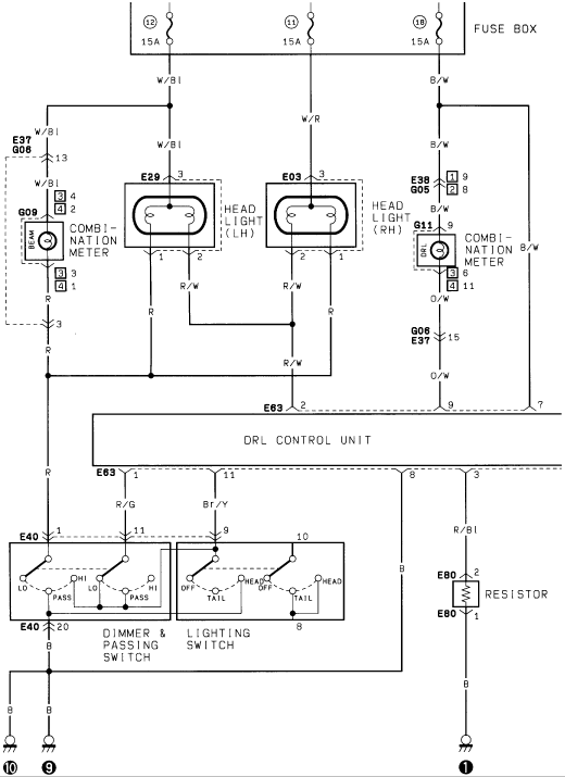
Wiring diagram of the headlight and daytime running light system showing the DRL control unit, headlights and lighting switches.
Part of 1986-1995 Suzuki Samurai Wiring Diagrams
This document is a single-page automotive wiring diagram showing a headlamp circuit with a Daytime Running Light (DRL) control unit, uploaded as "Headlamp DTR.gif" for a 1986 Suzuki Samurai. Power feeds from the fuse box via three 15A fuses (positions 12, 11, and 18) on wires W/Bl, W/R, and B/W. The circuit includes the left-hand headlight (connector E29) and right-hand headlight (connector E03), each with a three-pin connection, plus high-beam (BEAM) and DRL indicator lamps in the combination meter (connectors G09 and G11). A central DRL CONTROL UNIT (connector E63) manages headlight operation, receiving inputs on pins 2, 9, and 7 and sending outputs through pins 1, 11, and 3. Below it, a combined DIMMER & PASSING SWITCH (LO/HI/PASS positions) and LIGHTING SWITCH (OFF/TAIL/HEAD positions) at connector E40 control lighting modes, and a RESISTOR (connector E80) sits in the DRL circuit on the right side. Wire colors identified throughout include W/Bl, W/R, B/W, R, R/W, O/W, R/G, Br/Y, R/Bl, and B, with multiple chassis grounds at the bottom. A reader can trace fuse feeds, connector pin numbers, wire colors, and switch logic for diagnosing headlamp or DRL faults.
Is this accurate? Sign in to help verify it.
Frequently asked questions
- Which fuses power the headlight/DRL circuit in this diagram?
- Three 15A fuses in the fuse box: positions 12 (wire W/Bl), 11 (wire W/R), and 18 (wire B/W).
- What connectors are used for the left and right headlights?
- The left headlight (LH) uses connector E29 and the right headlight (RH) uses connector E03; each shows pin 3 on the feed side and pins 1 and 2 on the ground/switch side with R and R/W wires.
- What connector is the DRL control unit on?
- The DRL CONTROL UNIT connects via connector E63, with inputs on pins 2, 9, and 7 and outputs on pins 1, 11, and 3.
- What positions do the dimmer and lighting switches have?
- The DIMMER & PASSING SWITCH has LO, HI, and PASS positions; the LIGHTING SWITCH has OFF, TAIL, and HEAD positions. Both are on connector E40.
- Is there a resistor in the DRL circuit?
- Yes, a RESISTOR at connector E80 (pins 1 and 2) is fed by an R/Bl wire from DRL control unit pin 3 and grounds through a B wire.
Comments
More from this build














No comments yet.