Home/
Registry/
Suzuki/
Samurai/
1986-1995/
“Little Blue”/
Photo
supermotors.net/registry/media/420690
Suzuki Samurai Power Distribution Wiring Diagram - Main Fuse, Battery, Fuses
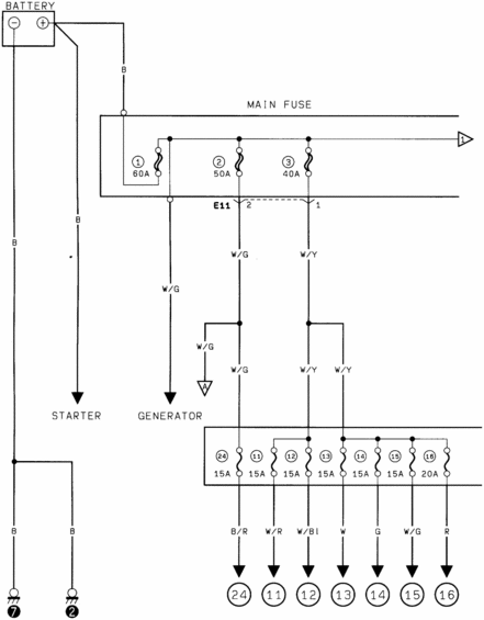
Power-distribution wiring schematic: battery to starter and generator with main fuses 60A/50A/40A (E11) feeding a fuse block of seven 15A/20A fuses (#11-#16, #24) on circuits B/R, W/R, W/Bl, W, G, W/G, R.
This document is a power distribution wiring diagram, uploaded as one page of a multi-page factory-style wiring diagram set for a 1986 Suzuki Samurai. It shows the battery with its positive (B wire) feed to the starter and to the MAIN FUSE block, which contains three high-amperage fuses: fuse 1 (60A), fuse 2 (50A), and fuse 3 (40A). Output from the main fuse block passes through connector E11 (pins 1 and 2) on white/green (W/G) and white/yellow (W/Y) wires. A W/G wire also feeds the generator (alternator), and a W/G branch goes to a diagram continuation point labeled 'A'. The W/G and W/Y feeds then supply a secondary fuse block containing fuses 24, 11, 12, 13, 14, and 15 (all 15A) plus fuse 16 (20A). Each fuse output leaves on a color-coded wire (B/R, W/R, W/Bl, W, G, W/G, R) toward numbered circuit continuation points (circles 24, 11–16) that connect to other pages of the diagram set. Battery negative and a second black (B) wire are shown grounding at points 7 and 2. Readers can learn main fuse ratings, branch fuse amperages, and the wire colors feeding each fused circuit.
Is this accurate? Sign in to help verify it.
Frequently asked questions
- What are the main fuse ratings in this Suzuki Samurai power distribution diagram?
- The MAIN FUSE block contains fuse 1 rated 60A, fuse 2 rated 50A, and fuse 3 rated 40A.
- What amperage are the secondary fuses shown in this diagram?
- Fuses 24, 11, 12, 13, 14, and 15 are all 15A, and fuse 16 is 20A.
- What wire colors leave the secondary fuse block?
- Fuse 24 outputs on B/R, fuse 11 on W/R, fuse 12 on W/Bl, fuse 13 on W, fuse 14 on G, fuse 15 on W/G, and fuse 16 on R.
- What wire feeds the generator in this diagram?
- A W/G (white/green) wire from the main fuse area feeds the GENERATOR.
- What connector links the main fuse block outputs in this diagram?
- Connector E11 is shown, with pin 2 carrying a W/G wire from fuse 2 and pin 1 carrying a W/Y wire from fuse 3.
Comments
More from this build














No comments yet.