Home/
Registry/
Suzuki/
Samurai/
1986-1995/
“Little Blue”/
Photo
supermotors.net/registry/media/420693
Suzuki Samurai Rear Wiper & Washer Motor Wiring Diagram - Switch, Fuses
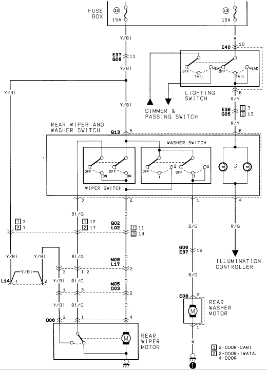
Rear wiper/washer and dash-illumination wiring schematic: 15A fuses feed rear wiper/washer switch (G13), rear wiper motor (O06) and rear washer motor (E08); ties to lighting switch, dimmer and illumination controller.
This is a scanned wiring diagram for the rear wiper and rear washer circuit, uploaded to a 1986 Suzuki Samurai gallery. Power originates at the fuse box from two 15A fuses (positions 20 and 13). Fuse 20 feeds a Yellow/Blue (Y/Bl) wire through connector E37/G06 pin 11 to the rear wiper and washer switch (connector G13, pin 5). Fuse 13 feeds a White wire through E40 pin 10 to the lighting switch (OFF/TAIL/HEAD positions), which supplies R/Y through E38/G05 to the switch illumination bulbs; a Red/Green (R/G) output goes to the illumination controller. The combination rear wiper/washer switch contains a wiper switch (OFF/ON), a washer switch (OFF/I), and illumination lamps. Wiper output travels on Blue/Green (Bl/G) and Orange (O) wires through connectors G02/L02, M08/L17, M05/O03 and O06 to the rear wiper motor, which includes an internal park switch and grounds locally. Washer output travels on Black/Green (B/G) through G06/E37 pin 16 and connector E08 to the rear washer motor, grounding on a Black wire. A footnote legend distinguishes pin assignments between 2-door CAMI, 2-door IWATA, and 4-door body variants. The diagram also references the dimmer & passing switch circuit branching from the lighting switch.
Is this accurate? Sign in to help verify it.
Frequently asked questions
- What fuses power the rear wiper and washer circuit?
- Two 15A fuses in the fuse box: position 20 (feeding a Y/Bl wire to the wiper/washer switch) and position 13 (feeding a W wire to the lighting switch for illumination).
- What wire colors go to the rear wiper motor?
- Blue/Green (Bl/G) and Orange (O) wires run from the rear wiper and washer switch through connectors G02/L02, M08/L17, M05/O03 and O06 to the rear wiper motor, with Yellow/Blue (Y/Bl) feed wiring also shown.
- How is the rear washer motor wired?
- A Black/Green (B/G) wire runs from the switch through connector G06/E37 pin 16 to connector E08 pin 2 at the rear washer motor; the motor grounds through a Black (B) wire from pin 1.
- What do the [1] and [2] footnote symbols mean on this diagram?
- [1] denotes 2-DOOR·CAMI and [2] denotes 2-DOOR·IWATA and 4-DOOR variants, indicating different connector pin numbers by body style/build plant.
- How is the switch illumination powered?
- Fuse 13 (15A) feeds the lighting switch via a White wire; in TAIL/HEAD positions, power flows on R/Y through connector E38/G05 to the ILL bulbs in the rear wiper/washer switch, with R/G output to the illumination controller.
Comments
More from this build














No comments yet.