Home/
Registry/
Suzuki/
Samurai/
1986-1995/
“Little Blue”/
Photo
supermotors.net/registry/media/420691
Suzuki Samurai Ignition Switch & Fuse Box Power Distribution Wiring Diagram
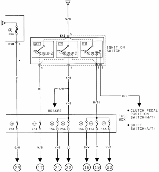
Factory power-distribution wiring diagram of the ignition switch (ACC/ON/ST) feeding the fuse box, listing individual fuse amperage and the clutch-pedal-position (M/T) / shift switch (A/T) inputs.
This is a power distribution wiring diagram (page from a multi-page Suzuki wiring diagram set) showing how battery/ignition power flows from a 30A main fuse (fuse 4, connector E10) through the ignition switch (connector E42, terminal 5, fed by a W/G wire) and into the fuse box. The ignition switch is drawn in three internal states — ACC, ON, and ST — showing which contacts (LOCK, ACC, IG2, IG1, ST) close in each key position. Switch outputs leave on terminals 4 (Bl wire), 7 (Y/B), 3 (B/Bl) and 6 (B/R). The Y/B feed also branches to a circuit breaker ("BRAKER"), and the B/R wire goes to the clutch pedal position switch (manual transmission) or shift switch (automatic transmission). Inside the fuse box, seven fuses are shown with amperages and output wire colors: fuse 23 (20A, G/R), fuse 17 (20A, W/B), fuse 21 (15A, Y/G), fuse 22 (25A, Lg), fuse 18 (15A, B/W), fuse 19 (15A, Y), and fuse 20 (15A, Y/Bl). Each fused output terminates at a numbered continuation symbol (23, 17, 21, 22, 18, 19, 20) leading to other diagram pages. A reader can learn fuse ratings, wire color codes, and ignition switch contact logic for this vehicle's power supply circuit.
Is this accurate? Sign in to help verify it.
Frequently asked questions
- What size is the main fuse feeding the ignition switch in this diagram?
- A 30A fuse (fuse position 4, at connector E10) feeds the ignition switch via a W wire; the switch input at connector E42 terminal 5 is a W/G wire.
- What fuse amperages are shown in the fuse box on this diagram?
- Fuse 23 – 20A, fuse 17 – 20A, fuse 21 – 15A, fuse 22 – 25A, fuse 18 – 15A, fuse 19 – 15A, and fuse 20 – 15A.
- Where does the B/R wire from the ignition switch (terminal 6) go?
- To the clutch pedal position switch on manual transmission (M/T) vehicles, or the shift switch on automatic transmission (A/T) vehicles.
- Which ignition switch terminals are hot in which key position?
- The diagram shows three states: in ACC, ON, and ST the switch closes different combinations of the LOCK, ACC, IG2, IG1 and ST contacts, with outputs on terminals 4 (Bl), 7 (Y/B), 3 (B/Bl) and 6 (B/R).
- What wire colors leave the fuse box on each fuse?
- Fuse 23: G/R, fuse 17: W/B, fuse 21: Y/G, fuse 22: Lg, fuse 18: B/W, fuse 19: Y, fuse 20: Y/Bl.
Comments
More from this build














No comments yet.