Home/
Registry/
Suzuki/
Samurai/
1986-1995/
“Little Blue”/
Photo
supermotors.net/registry/media/420708
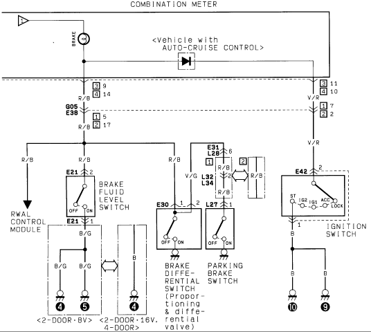
Suzuki Brake Warning Lamp Wiring Diagram - Fluid Level, Parking Brake, RWAL
Reference · 1986-1995 SamuraiAll 73 wiring diagrams
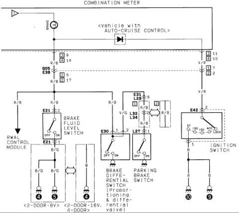
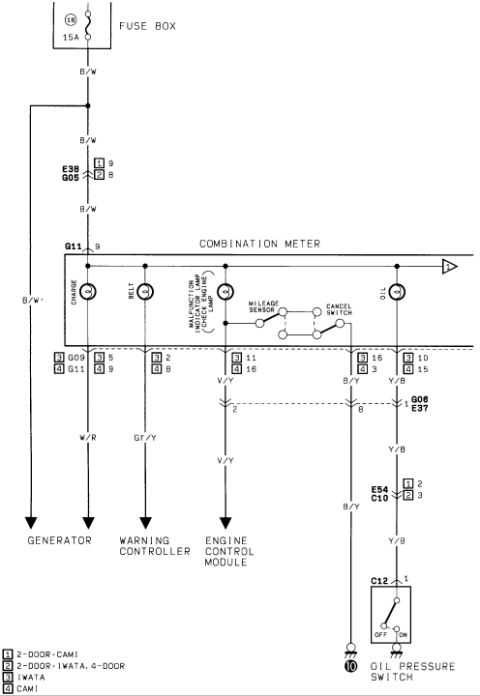
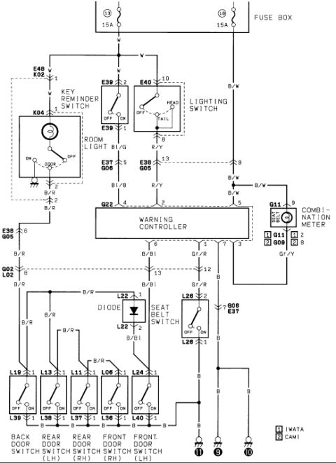
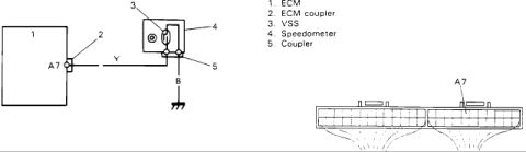
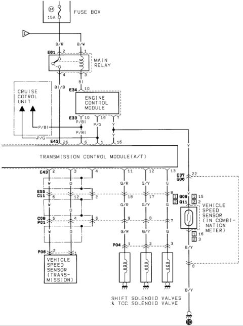
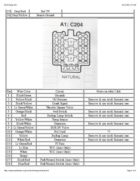
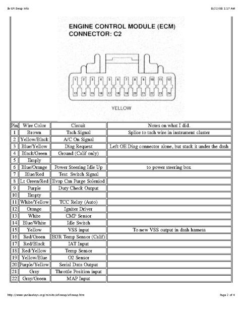
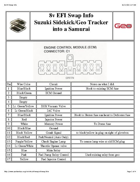
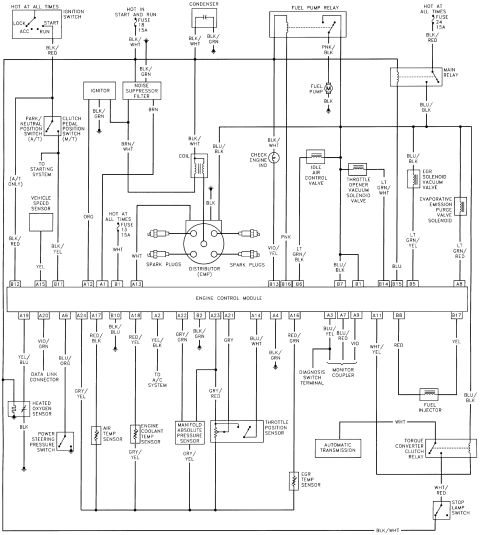
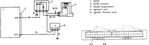
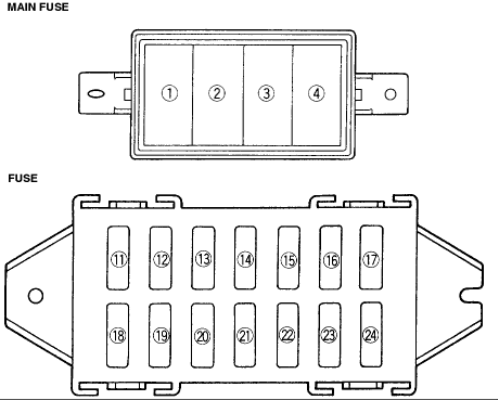

Wiring diagram of the brake warning circuit showing fluid level, brake differential and parking brake switches with the ignition switch.
Part of 1986-1995 Suzuki Samurai Wiring Diagrams
This is one page of a factory-style wiring diagram covering the brake warning lamp circuit in the combination meter. It shows the BRAKE warning indicator fed through the combination meter (pins 9/14 and 11/10 on connectors [3] and [4]), with a diode branch noted for vehicles equipped with auto-cruise control. The warning lamp circuit is grounded through several switches wired in parallel: the brake fluid level switch (connector E21), the brake differential switch on the proportioning and differential valve (connector E30), and the parking brake switch (connector L27). A branch also runs to the RWAL (rear-wheel anti-lock) control module. The right side of the diagram shows the ignition switch (connector E42) with positions ST, IG2, IG1, ACC, and LOCK, grounding through points 10 and 9. Wire colors are labeled throughout: R/B (red/black), V/R (violet/red), B/G (black/green), V/G (violet/green), and B (black). Grounding variations are shown for 2-door 8V versus 2-door 16V and 4-door body styles. Connector identifiers visible include G05, E38, E21, E30, E31, L27, L28, L32, L34, and E42. A reader can trace how the brake warning lamp is triggered by low brake fluid, parking brake application, or brake pressure differential.
Is this accurate? Sign in to help verify it.
Frequently asked questions
- What switches can turn on the brake warning lamp according to this diagram?
- The brake fluid level switch (connector E21), the brake differential switch on the proportioning and differential valve (connector E30), and the parking brake switch (connector L27) all ground the brake warning lamp circuit.
- What wire colors are used in the brake warning lamp circuit?
- R/B (red/black) on the warning lamp side, V/R (violet/red) from the ignition switch side, V/G (violet/green) to the brake differential switch, B/G (black/green) grounds from the brake fluid level switch, and B (black) grounds.
- Does this circuit connect to the anti-lock brake system?
- Yes, an R/B wire branch from the brake warning lamp circuit runs to the RWAL control module.
- What is different for vehicles with auto-cruise control?
- The diagram shows a diode in the combination meter branch labeled '<Vehicle with AUTO-CRUISE CONTROL>'.
- What ignition switch positions are shown?
- Connector E42 shows the ignition switch with positions ST, IG2, IG1, ACC, and LOCK.






No comments yet.