Home/
Registry/
Suzuki/
Samurai/
1986-1995/
“Little Blue”/
Photo
supermotors.net/registry/media/420707
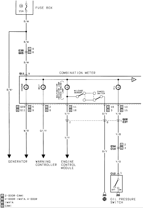
Suzuki Warning Lamp Wiring Diagram - Charge, Oil, Check Engine Lamps
Reference · 1986-1995 SamuraiAll 73 wiring diagrams
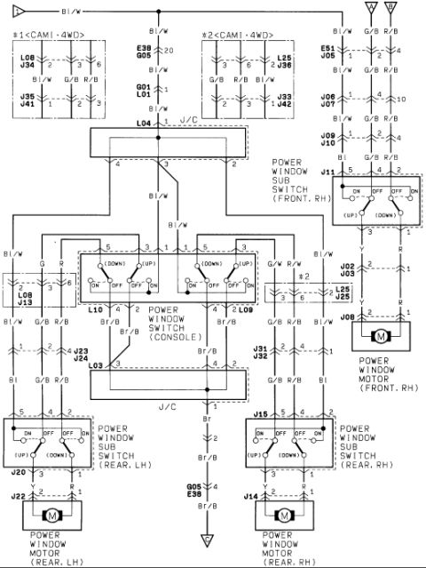
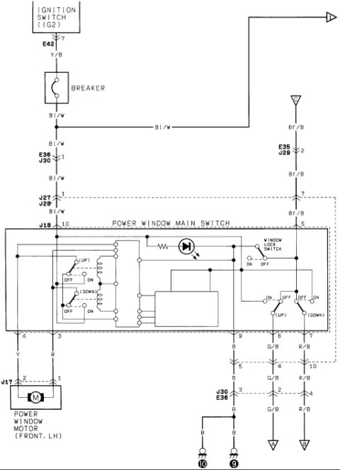
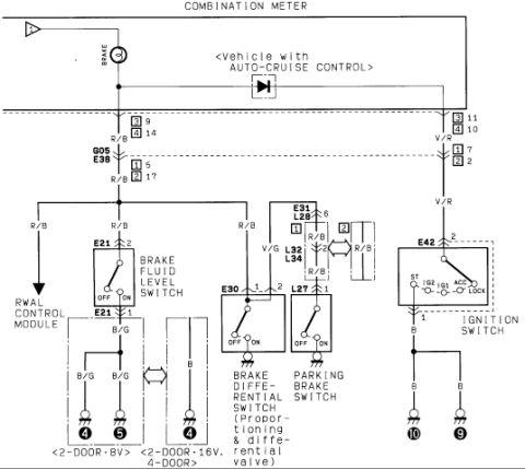
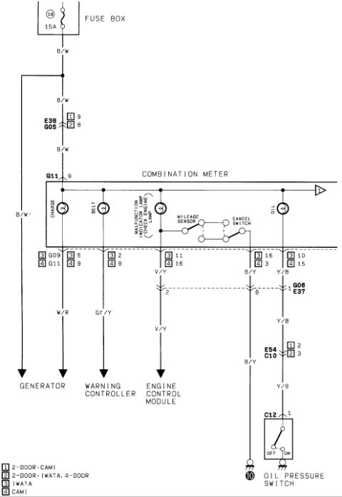
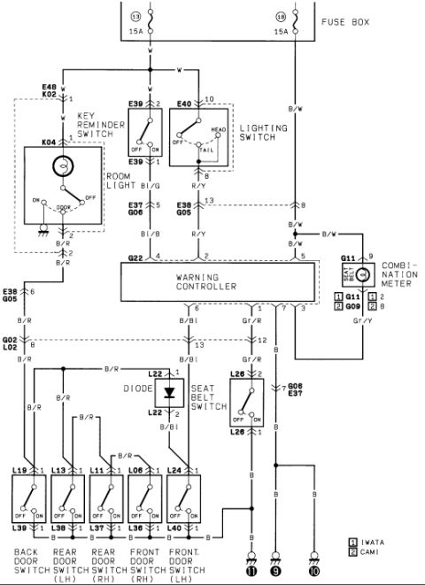
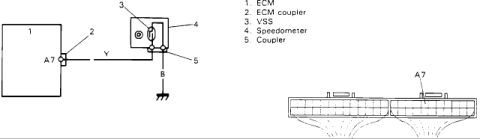
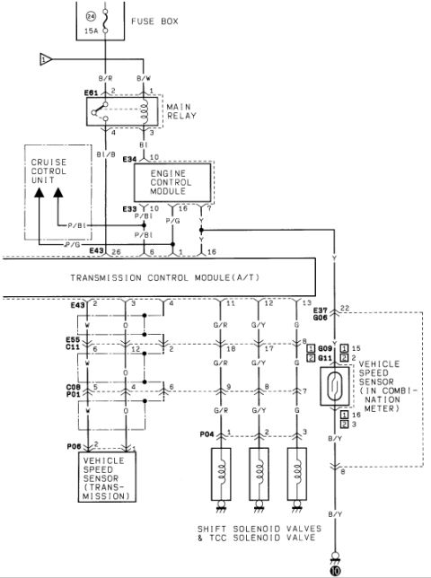
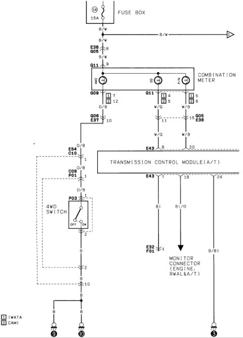
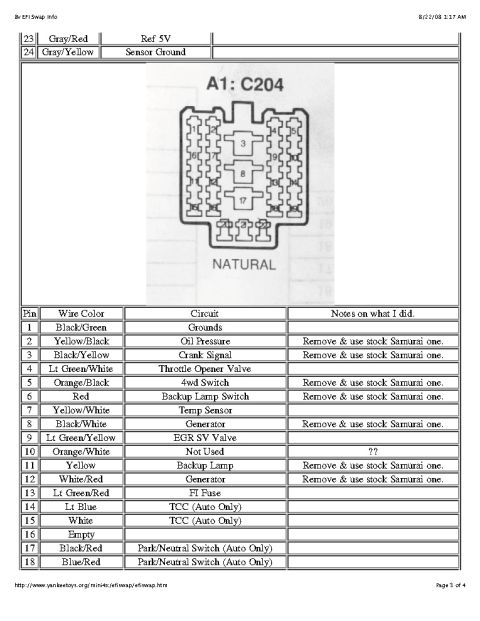
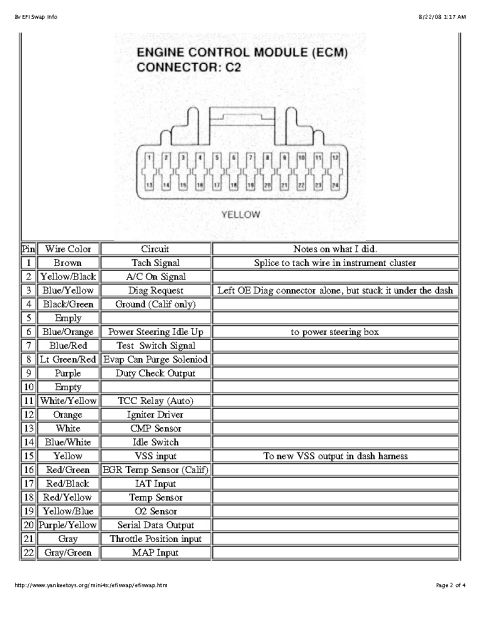
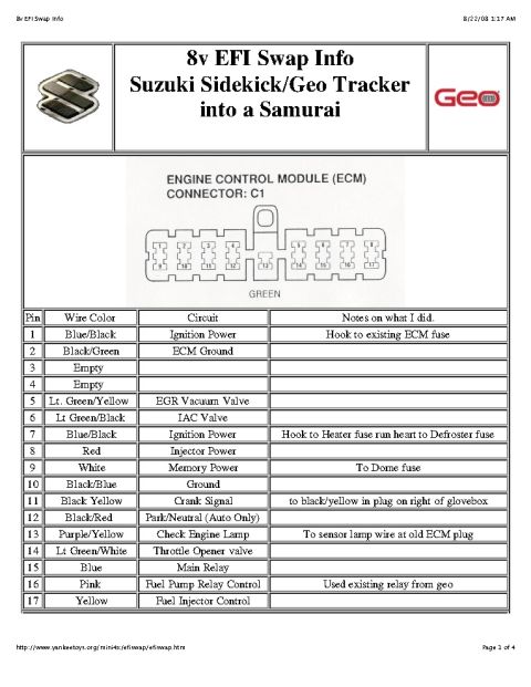

Wiring diagram of the combination meter warning lights showing charge, seat belt, malfunction indicator and oil pressure switch circuits.
Part of 1986-1995 Suzuki Samurai Wiring Diagrams
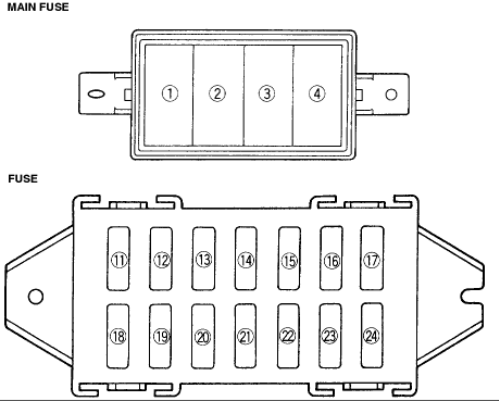
This is a scanned wiring diagram covering the warning lamp circuits in the combination meter (instrument cluster) of a Suzuki vehicle. Power feeds from a 15A fuse in the fuse box (position 18) through a B/W (black/white) wire, passing through connectors E38/G05 to combination meter connector G11 pin 9. Inside the combination meter, the diagram shows the CHARGE lamp, BELT lamp, MALFUNCTION INDICATOR LAMP (CHECK ENGINE LAMP) with associated mileage sensor and cancel switch, and OIL pressure warning lamp. Output circuits leave the cluster via connectors G09/G11 (pins vary by build: pins 5, 2/8, 11/16, 16/14, 10/15) and run as follows: W/R wire to the GENERATOR (charge lamp), Gr/Y wire to the WARNING CONTROLLER (belt lamp), V/Y wire to the ENGINE CONTROL MODULE (check engine lamp), and Y/B wire through connectors G06/E37, E54/C10, and C12 to the OIL PRESSURE SWITCH, which grounds the circuit when oil pressure is low (OFF/ON positions shown). A legend distinguishes wiring variations by body style and assembly plant: [1] 2-Door CAMI, [2] 2-Door Iwata and 4-Door, [3] Iwata, [4] CAMI. The diagram is useful for diagnosing charge, seat belt, check engine, and oil pressure warning lamp faults.
Is this accurate? Sign in to help verify it.
Frequently asked questions
- What fuse powers the warning lamps in the combination meter?
- A 15A fuse in the fuse box (position 18) feeds the combination meter warning lamps via a B/W (black/white) wire through connectors E38/G05 to G11 pin 9.
- What wire color goes from the charge warning lamp to the generator?
- A W/R (white/red) wire runs from the CHARGE lamp in the combination meter to the generator.
- How is the check engine (malfunction indicator) lamp wired?
- The malfunction indicator lamp, with its mileage sensor and cancel switch, connects through a V/Y (violet/yellow) wire to the Engine Control Module. Pin 11 or 16 is used depending on the build (Iwata vs. CAMI).
- What circuit controls the oil pressure warning lamp?
- The OIL lamp is fed from the meter through a Y/B (yellow/black) wire, passing through connectors G06/E37, E54/C10, and C12 to the oil pressure switch, which grounds the circuit (OFF/ON positions shown).
- What do the numbered legend symbols mean on this diagram?
- They indicate build variants: [1] 2-Door CAMI, [2] 2-Door Iwata and 4-Door, [3] Iwata-built, [4] CAMI-built vehicles.






No comments yet.