Home/
Registry/
Suzuki/
Samurai/
1986-1995/
“Little Blue”/
Photo
supermotors.net/registry/media/420706
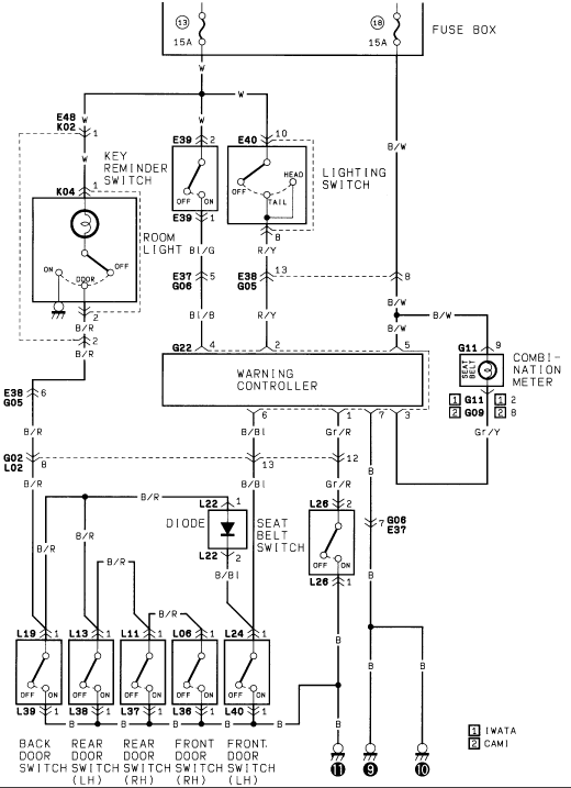
Suzuki Samurai Warning Controller Wiring Diagram - Seat Belt & Door Switches
Reference · 1986-1995 SamuraiAll 73 wiring diagrams
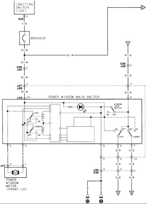
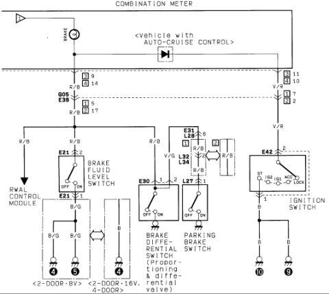
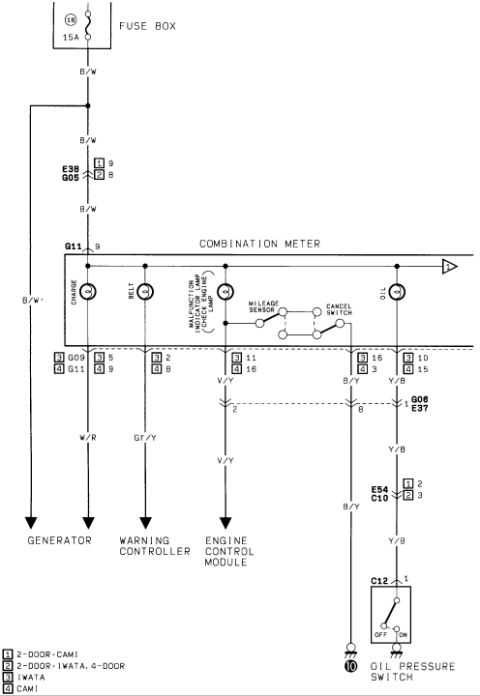
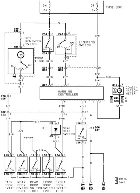
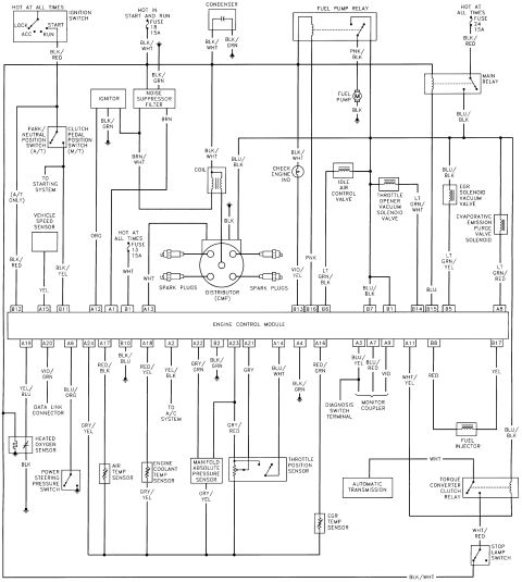
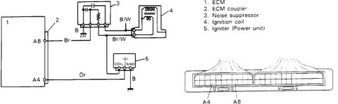
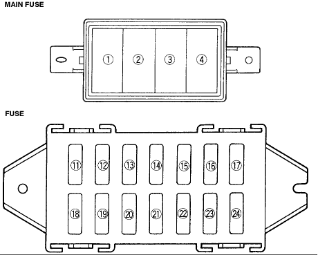

Warning-system wiring schematic: 15A fuses feed warning controller (G22), key reminder switch, seat-belt switch with diode, and back/front/rear door switches (L19/L13/L11/L06/L24) to the combination meter.
Part of 1986-1995 Suzuki Samurai Wiring Diagrams
This scanned page is a factory-style wiring diagram for the warning (chime/warning controller) circuit of a Suzuki vehicle, uploaded to a 1986 Suzuki Samurai gallery. Power comes from fuse box positions 13 and 18, both rated 15A. The diagram traces the White (W) and Black/White (B/W) feeds to the key reminder switch (connectors E48/K02), room light (K04, with ON/DOOR/OFF positions), and lighting switch (connectors E39 and E40, with OFF/ON and OFF/TAIL/HEAD positions). The central WARNING CONTROLLER (connector G22) receives inputs on Blue/Black (Bl/B), Red/Yellow (R/Y), Black/White (B/W) and Black/Red (B/R) wires and drives the seat-belt indicator lamp in the combination meter (connectors G11/G09, wire Gr/Y) and monitors a diode-protected seat belt switch (L22, L26, wires Gr/R and B/Bl). Five door switches, back door (L19/L39), rear LH (L13/L38), rear RH (L11/L37), front RH (L06/L36) and front LH (L24/L40), feed the circuit via Black/Red wires and ground through Black wires at ground points 11, 9 and 10. A legend notes variations for IWATA and CAMI assembly plants. Readers can learn fuse ratings, connector IDs, pin numbers and wire color codes for diagnosing the seat belt/key/door warning system.
Is this accurate? Sign in to help verify it.
Frequently asked questions
- What fuses power the warning controller circuit?
- Fuse box positions 13 and 18, each rated 15A, feed the circuit via White (W) and Black/White (B/W) wires.
- What connector is used for the warning controller?
- The warning controller connects through connector G22, with pins including 4, 2, 5, 6, 1, 7, 3, 12 and 13 shown on the diagram.
- What wire color goes to the seat belt indicator in the combination meter?
- A Gray/Yellow (Gr/Y) wire connects the combination meter BELT lamp (connectors G11/G09) to the warning controller, with Black/White (B/W) as the feed.
- Which connectors are used for the door switches?
- Back door switch L19/L39, rear door switch LH L13/L38, rear door switch RH L11/L37, front door switch RH L06/L36, and front door switch LH L24/L40. All are fed by Black/Red (B/R) wires and ground through Black (B) wires.
- What do the [1] and [2] legend symbols mean on this diagram?
- The legend states [1] = IWATA and [2] = CAMI, indicating connector differences by assembly plant.






No comments yet.