Home/
Registry/
Ford/
Crown Victoria/
1998-2011/
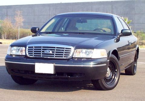
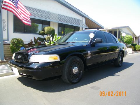
“Flying Snow”/
Photo
supermotors.net/registry/media/437225
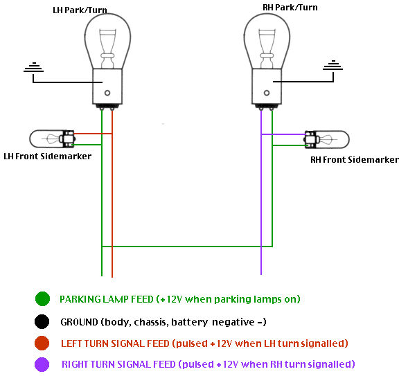
Front Sidemarker & Park/Turn Lamp Wiring Diagram: Alternating Flash Mod
Reference · 1998-2011 Crown VictoriaAll 29 wiring diagrams




Wiring diagram of LH/RH park/turn lamps and front sidemarkers with a color-coded legend for parking, ground, and turn-signal feeds.
Part of 1998-2011 Ford Crown Victoria Wiring Diagrams
This document is a simple color-coded wiring diagram (titled by the uploader as 'Side marker after') showing how front parking/turn signal lamps and front sidemarker lamps are wired so that the sidemarkers flash alternately with the turn signals. It depicts LH and RH dual-filament park/turn bulbs, each grounded to the chassis and fed by a green parking lamp feed (+12V when parking lamps are on) plus a turn signal feed, red for the left turn signal (pulsed +12V when LH turn is signalled) and purple for the right turn signal (pulsed +12V when RH turn is signalled). Each front sidemarker bulb is connected between the parking lamp feed and its respective side's turn signal feed rather than to ground. A four-entry legend defines the wire colors: green = parking lamp feed, black = ground (body, chassis, battery negative), red = left turn signal feed, purple = right turn signal feed. From this diagram a reader can learn the post-modification wiring arrangement that makes sidemarkers alternate-flash with the turn signals: when only the park lamps are on, the sidemarker completes its circuit through the turn filament; when the turn signal pulses, the voltage difference causes the sidemarker to flash opposite the turn lamp. No year, model, part numbers, fuse data, or connector details are shown.
Is this accurate? Sign in to help verify it.
Frequently asked questions
- What does the green wire represent in this diagram?
- The green wire is the parking lamp feed, which carries +12V when the parking lamps are on. It feeds both park/turn bulbs and both front sidemarkers.
- How are the front sidemarker lamps wired in this diagram?
- Each front sidemarker is wired between the green parking lamp feed and its side's turn signal feed, the LH sidemarker to the red left turn signal feed and the RH sidemarker to the purple right turn signal feed, instead of to ground.
- What do the red and purple wires do?
- Red is the left turn signal feed (pulsed +12V when the LH turn is signalled) and purple is the right turn signal feed (pulsed +12V when the RH turn is signalled).
- How are the park/turn bulbs grounded?
- Each LH and RH park/turn bulb is shown connected to a chassis ground symbol, defined in the legend as body, chassis, or battery negative.



No comments yet.