Home/
Registry/
Ford/
Bronco/
1987-1991/
“The OJ Special”/
Photo
supermotors.net/registry/media/493070
Rock Lights Wiring Diagram - Relay, DPST Switch, 20A Fuse (Ford Bronco Mod)

Reference · 1987-1991 BroncoAll 175 wiring diagrams
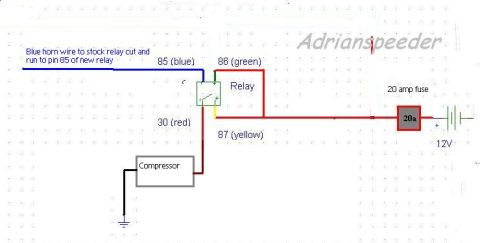
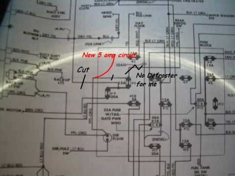
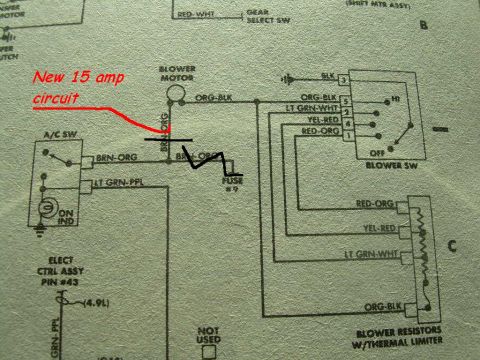
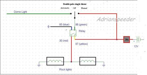
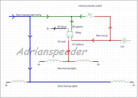

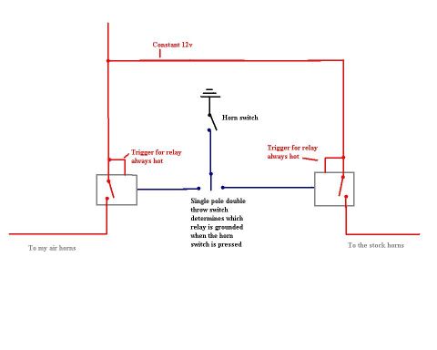



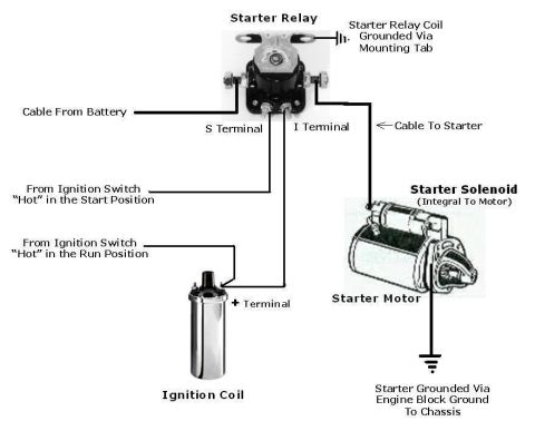
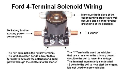








Wiring diagram showing rock lights wired through a DPST switch and relay with color-coded pins (85/86/30/87) and a 20A fuse to 12V.
Part of 1987-1991 Ford Bronco Wiring Diagrams
This document is a hand-drawn style wiring diagram (credited to "Adrianspeeder") showing how to wire aftermarket rock lights using a standard automotive relay and a double pole single throw switch with three positions labeled Automatic, Off, and Manual. In Automatic mode the switch connects the relay trigger to the vehicle's dome light circuit (shown as a green wire), so the rock lights turn on with the dome light; in Manual mode the trigger connects directly to 12V power (red wire). The relay pins are labeled with their wire colors: pin 85 (blue) to ground, pin 86 (green) to the switch, pin 30 (red), and pin 87 (yellow). Power from the 12V battery passes through a 20-amp fuse (labeled "20a") before reaching the relay and the manual side of the switch. The switched output feeds two rock light coils/lamps wired in parallel, each grounded to chassis ground. A reader can learn the relay pinout, wire color assignments, fuse rating (20A), and the switching logic needed to make rock lights operate either automatically with the dome light or manually via the switch.
Is this accurate? Sign in to help verify it.
Frequently asked questions
- What fuse size does this rock lights wiring diagram use?
- A 20 amp fuse (labeled '20a') is shown inline between the 12V battery positive and the relay/switch circuit.
- What are the relay pin wire colors in this diagram?
- Pin 85 is blue (to ground), pin 86 is green (to the switch), pin 30 is red (power in), and pin 87 is yellow (output to the rock lights).
- What kind of switch does this rock light circuit use?
- A double pole single throw switch with three positions: Automatic, Off, and Manual.
- How does the Automatic mode work?
- In the Automatic position the switch connects the relay trigger (pin 86, green wire) to the dome light circuit, so the rock lights come on whenever the dome light is on.
- How are the rock lights themselves wired?
- Two rock lights are wired in parallel, fed by the relay pin 87 (yellow/red output) with each light grounded to chassis ground.






No comments yet.