Home/
Registry/
Ford/
Bronco/
1987-1991/
“The OJ Special”/
Photo
supermotors.net/registry/media/459342
Ford Bronco Headlight Relay Wiring Diagram - Low/High Beam Relay Upgrade Schematic

Reference · 1987-1991 BroncoAll 175 wiring diagrams
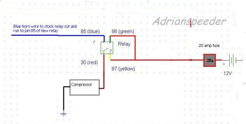
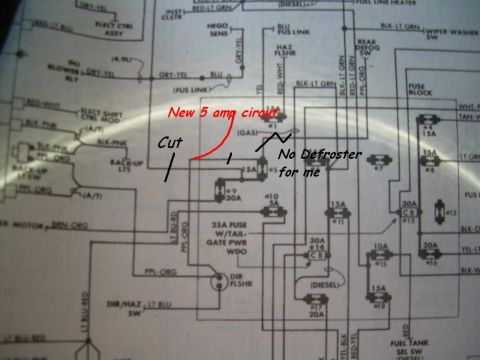
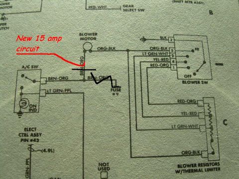
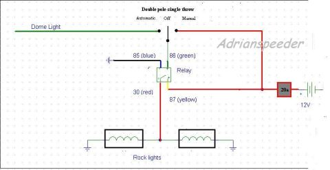
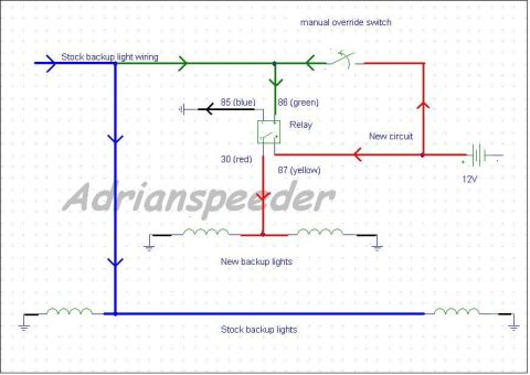

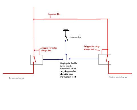


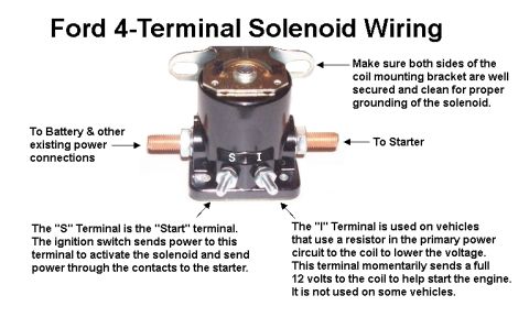
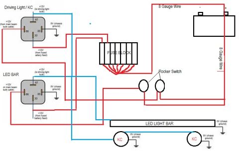








Wiring diagram for headlight relays showing low-beam and high-beam relays with color-coded terminal numbers.
Part of 1987-1991 Ford Bronco Wiring Diagrams
This document is a hand-drawn (CAD-style) headlight relay wiring schematic uploaded to a 1988 Ford Bronco gallery. It shows how to wire two relays, a LowBeamRelay and a HighBeamRelay, to power the headlamps directly from a constant 12V battery source rather than through the stock switch. Battery power (Constant12V) feeds two 10-amp fuses; each fuse supplies relay pin 30 (Red wire). Each relay's pin 87 (Yellow) output goes to the headlamp filaments (drawn as coils, two filaments per side, grounded at the chassis). The relay coils are triggered on pin 85 (Blue), with pin 86 (Green) routed to the switches: the LowBeamRelay is controlled by the StockHeadLightSwitch, and the HighBeamRelay is controlled by a HighBeamToggle switch. Wire colors are labeled at every relay pin (30 Red, 85 Blue, 86 Green, 87 Yellow). The diagram gives no year, model, part numbers, or engine applicability, it is a generic relay-conversion schematic commonly used to upgrade headlight brightness and reduce load on the factory headlight switch. A reader can learn the fuse ratings (10A each), the relay pinout wiring colors, and how the stock switch and an added toggle trigger the low- and high-beam relays.
Is this accurate? Sign in to help verify it.
Frequently asked questions
- What fuse ratings are used in this headlight relay wiring diagram?
- Two 10-amp (10a) fuses, one for each relay circuit, fed from the Constant 12V battery source.
- What wire colors are used on the relay pins?
- Pin 30 is Red, pin 85 is Blue, pin 86 is Green, and pin 87 is Yellow on both the LowBeamRelay and HighBeamRelay.
- How is the low beam relay triggered?
- The LowBeamRelay coil (pins 85 Blue / 86 Green) is triggered through the StockHeadLightSwitch.
- What controls the high beam relay?
- A separate switch labeled HighBeamToggle triggers the HighBeamRelay coil, wired downstream of the StockHeadLightSwitch circuit.
- Where do the relays get their power?
- Both relay pin 30 (Red) connections receive Constant 12V battery power through individual 10a fuses.






No comments yet.