Home/
Registry/
Ford/
Bronco/
1987-1991/
“Eddie Bauer”/
Photo
supermotors.net/registry/media/1109637
Ford 4-Terminal Starter Solenoid Wiring Diagram - S & I Terminal Functions

Reference · 1987-1991 BroncoAll 175 wiring diagrams

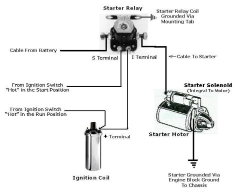
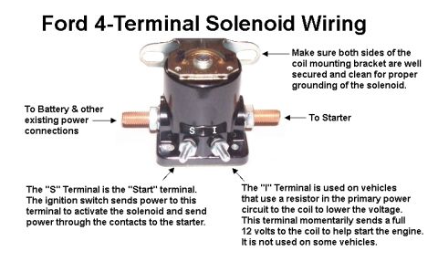
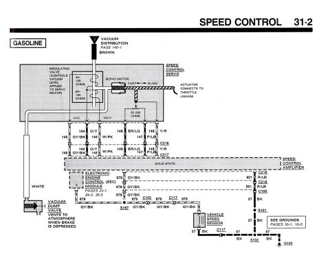
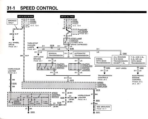
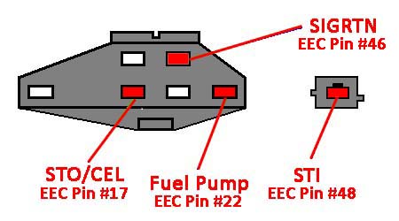












Annotated Ford 4-terminal starter solenoid wiring diagram explaining the battery, starter, S start terminal, and I terminal connections.
Part of 1987-1991 Ford Bronco Wiring Diagrams
This document is an annotated photograph explaining the wiring of a Ford 4-terminal starter solenoid (starter relay). The image shows the solenoid mounted on its bracket with callouts identifying each connection point. The left large stud connects to the battery and other existing power connections, while the right large stud connects to the starter. Two small front terminals are labeled "S" and "I": the "S" (Start) terminal receives power from the ignition switch to activate the solenoid, closing the contacts to send power to the starter. The "I" terminal is used on vehicles with a resistor in the primary power circuit to the ignition coil; during cranking it momentarily supplies a full 12 volts to the coil to aid starting, though it is not used on some vehicles. The document also stresses that both sides of the solenoid's mounting bracket must be well secured and clean, since the bracket provides the ground path for the solenoid. A reader can learn which wire goes to which terminal, the purpose of the S and I terminals, and the importance of proper grounding through the mounting bracket. No specific year, model, or part numbers are stated.
Is this accurate? Sign in to help verify it.
Frequently asked questions
- What is the "S" terminal on a Ford starter solenoid for?
- The "S" terminal is the "Start" terminal. The ignition switch sends power to this terminal to activate the solenoid and send power through the contacts to the starter.
- What does the "I" terminal on a Ford solenoid do?
- The "I" terminal is used on vehicles that use a resistor in the primary power circuit to the coil to lower the voltage. It momentarily sends a full 12 volts to the coil to help start the engine. It is not used on some vehicles.
- Which large terminal connects to the battery and which to the starter?
- The large terminal on the left (as shown) goes to the battery and other existing power connections; the large terminal on the right goes to the starter.
- How is the solenoid grounded?
- Through its mounting bracket, the document says to make sure both sides of the coil mounting bracket are well secured and clean for proper grounding of the solenoid.






No comments yet.