Home/
Registry/
Ford/
Bronco/
1987-1991/
“The OJ Special”/
Photo
supermotors.net/registry/media/493101
1988 Ford Bronco Blower Motor Wiring Diagram - Fan Switch & Resistor Wire Colors

Reference · 1987-1991 BroncoAll 175 wiring diagrams
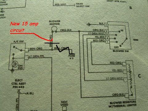










HVAC blower-motor wiring diagram with color-coded wires, blower switch, and a marked new 15-amp fused circuit annotation.
Part of 1987-1991 Ford Bronco Wiring Diagrams
This is a scanned portion of a factory-style wiring diagram for the blower motor / HVAC blower circuit, uploaded to a 1988 Ford Bronco gallery. It shows the blower motor fed by a BRN-ORG wire (routed through 'FUSE #9') and an ORG-BLK wire running to the blower switch. The blower switch connector is detailed with five pins: pin 3 BLK (ground), pin 5 ORG-BLK (HI), pin 2 LT GRN-WHT, pin 4 YEL-RED, and pin 1 RED-ORG, plus an OFF position. Below the switch, the blower resistors with thermal limiter (block C) are shown with RED-ORG, YEL-RED, LT GRN-WHT, and ORG-BLK leads for the various fan speeds. The A/C switch is shown with BRN-ORG and LT GRN-PPL wires and an ON indicator, and an electronic control assembly at pin #43 is noted with a (4.9L) engine callout and GRN-PPL wire. A gear select switch (RED-WHT wire) and shift motor assembly appear at the top edge. The uploader has hand-annotated the diagram in red ('New 15 amp circuit') with a drawn-in fuse symbol on the BRN-ORG blower feed, documenting an added 15-amp inline fuse modification to the blower motor power wire.
Is this accurate? Sign in to help verify it.
Frequently asked questions
- What wire colors go to the blower switch?
- Per the diagram: pin 3 BLK (ground), pin 5 ORG-BLK (HI speed), pin 2 LT GRN-WHT, pin 4 YEL-RED, and pin 1 RED-ORG, plus an OFF position.
- What wires connect to the blower resistors?
- The blower resistors with thermal limiter connect via RED-ORG, YEL-RED, LT GRN-WHT, and ORG-BLK wires.
- Which fuse feeds the blower motor circuit?
- The BRN-ORG feed wire is shown running through Fuse #9. The uploader also hand-annotated a 'New 15 amp circuit' with an added fuse drawn on the BRN-ORG wire at the blower motor.
- What wires are at the A/C switch?
- The A/C switch shows a BRN-ORG wire and a LT GRN-PPL wire, plus an ON indicator lamp.
- What does the red handwritten note mean?
- The red annotation reads 'New 15 amp circuit' and points to a hand-drawn fuse symbol added on the BRN-ORG blower motor feed wire, documenting an added 15A inline fuse.






No comments yet.