Home/
Registry/
Ford/
Bronco/
1987-1991/
“The OJ Special”/
Photo
supermotors.net/registry/media/505597
Ford Bronco Air Horn Compressor Relay Wiring Diagram - Pins 85/86/30/87, 20A Fuse

Reference · 1987-1991 BroncoAll 175 wiring diagrams
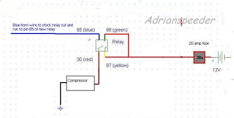
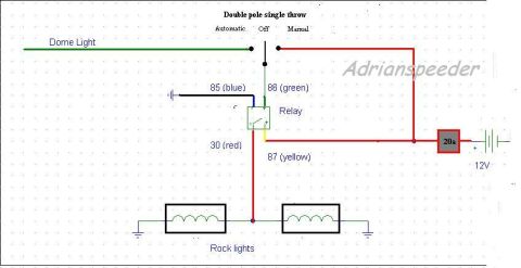

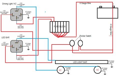








Wiring diagram showing an air-horn compressor wired through a relay with color-coded pins and a 20-amp fuse to 12V.
Part of 1987-1991 Ford Bronco Wiring Diagrams
This document is a hand-drawn wiring diagram (watermarked "Adrianspeeder") showing how to wire an aftermarket air horn compressor to a standard 4-pin automotive relay, uploaded to the gallery of a 1988 Ford Bronco as "horn relay.jpg". The diagram shows the original blue horn wire from the stock relay being cut and connected to pin 85 (blue) of the new relay to act as the trigger signal. Pin 86 (green) provides the other side of the relay coil circuit, tied into the switched power line. Pin 87 (yellow) receives power from the vehicle's 12V source through a 20 amp fuse, and pin 30 (red) delivers switched power output to the compressor, which is grounded on its other terminal. From this diagram a reader can learn the correct relay pin assignments (85, 86, 30, 87), the color coding used for each wire (blue, green, red, yellow), the required fuse rating (20 amps), and the general layout for adding a relay-driven air horn compressor triggered by the factory horn circuit. The document contains no year, model, or part number information of its own.
Is this accurate? Sign in to help verify it.
Frequently asked questions
- Which relay pin does the stock horn wire connect to?
- The blue horn wire from the stock relay is cut and run to pin 85 of the new relay.
- What size fuse is used in this horn compressor relay circuit?
- A 20 amp fuse is placed between the 12V power source and the relay circuit.
- Which relay pin connects to the compressor?
- Pin 30 (red wire) of the relay connects to the compressor, which is grounded on its other terminal.
- What are the wire colors for each relay pin in this diagram?
- Pin 85 is blue, pin 86 is green, pin 30 is red, and pin 87 is yellow.
- Where does the relay get its power?
- Pin 87 (yellow) is fed from the 12V battery/source through a 20 amp fuse.






No comments yet.