Home/
Registry/
Ford/
LTD Crown Victoria/
1983-1991/
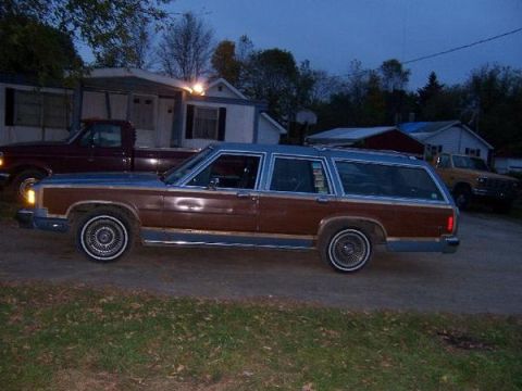
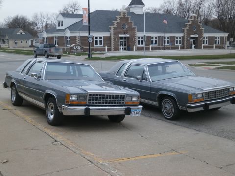
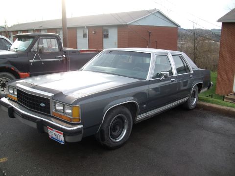
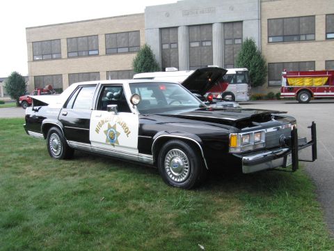
1985 Ford LTD Crown Victoria/
Photo
supermotors.net/registry/media/504699
1987 Ford Crown Victoria/Grand Marquis 5.0L SEFI EEC-IV Wiring Diagram

Automotive wiring diagram for the 5.0L SEFI EEC-IV system on a 1987 Ford LTD Crown Victoria with color-coded circuits and connectors.
Part of 1983-1991 Ford LTD Crown Victoria Wiring Diagrams
This document is a Mitchell Repair Information wiring diagram titled '5.0L SEFI EEC IV TESTING, Fig. 4: 5.0L SEFI EEC-IV Wir Diagram (Crown Victoria & Grand Marquis)' labeled for a 1987 Ford LTD Crown Victoria. It shows the complete engine control wiring for the 5.0L Sequential Electronic Fuel Injection system managed by the EEC-IV Electronic Control Assembly (ECA). The diagram maps the 60-pin ECA connector, listing pin numbers, signal names (KAPWR, ISC, FUEL PUMP, HEGO, IDM, ACT, MAP, VREF, SIG RTN, ECT, EVP, TP, STI, SPOUT, PIP, STO, V PWR, injector drivers, grounds), and the wire colors for each circuit. Connected components include the idle speed control solenoid, EEC-IV self-test connector, fuel pump and inertia switch, fuel pump relay, EEC power relay, MAP sensor, manifold charge temp sensor, engine coolant temp sensor, EGR valve position sensor, throttle position sensor, canister purge solenoid, thermactor TAD/TAB solenoids, EGR vent solenoid, A/C wide-open throttle relay, Tripminder module, left and right O2 sensors, TFI ignition module and coil, radio noise capacitor, and all eight fuel injectors with their individual wire colors (RED feed with TAN-based signal wires). A reader can trace any EEC-IV circuit by pin number and wire color for diagnosis or repair.
This document covers 1987, which may differ from this 1985 Ford LTD Crown Victoria.
Is this accurate? Sign in to help verify it.
Frequently asked questions
- What wire colors do the fuel injectors use on the 5.0L SEFI Crown Victoria?
- Each injector has a RED feed wire and an individual signal wire: #1 TAN, #2 TAN-WHT, #3 TAN-YEL, #4 TAN-BLK, #5 TAN-LT BLU, #6 TAN-LT GRN, #7 TAN-ORG, #8 TAN-RED.
- Which ECA pins are power and ground on the EEC-IV computer?
- V PWR is on pins 37 and 57 (RED wires), KAPWR is pin 1 (YEL from the starter fuse link), CASE GND is pin 20 (BLK), and PWR GND is on pins 40 and 60 (BLK-LT GRN).
- What wire colors go to the throttle position sensor?
- The throttle position sensor uses ORG-WHT (VREF), DK GRN-LT GRN (TP signal to ECA pin 47), and BLK-WHT (signal return).
- How is the fuel pump circuit wired in this diagram?
- The fuel pump connects with PNK-BLK and BLK wires through the inertia switch (shown NC) to the fuel pump relay, which is fed by YEL and ORG wires from the starter fuse link and connects TAN-LT GRN and RED wires; the ECA FUEL PUMP signal is TAN-LT GRN on pin 22.
- What are the oxygen sensor wire colors?
- The left O2 sensor uses DK BLU-LT GRN, BLK-LT GRN, and GRY-YEL; the right O2 sensor uses DK GRN-PPL, BLK-LT GRN, and GRY-YEL, with GRY-YEL also going to ignition switch pin A2.
Comments
More from this build









No comments yet.