Home/
Registry/
Ford/
Bronco/
1987-1991/
1988 Ford Bronco/
Photo
supermotors.net/registry/media/506512
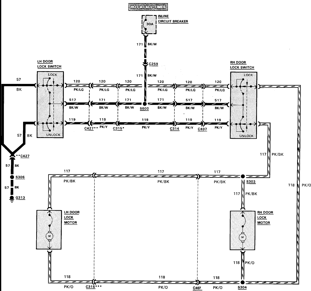
1988 Ford Bronco Power Door Lock Wiring Diagram - Switches, Motors & 30A Breaker
Reference · 1987-1991 BroncoAll 175 wiring diagrams
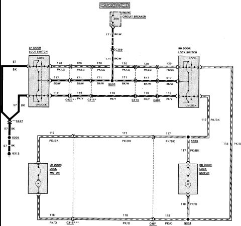






Wiring diagram of the power door lock circuit showing LH/RH lock switches and motors with color-coded wires and connector IDs.
Part of 1987-1991 Ford Bronco Wiring Diagrams
This document is a wiring diagram for a power door lock system, uploaded as applying to a 1988 Ford Bronco. It shows power supplied from a source that is HOT AT ALL TIMES through a 30-amp inline circuit breaker on circuit 171 (black/white), passing through connector C259 and splice S600 to feed both the LH and RH door lock switches. The two switches (each with LOCK and UNLOCK positions) are cross-wired via circuits 120 (pink/light green) for lock, 171/517 (black/white) for power feed, and 119 (pink/yellow) for unlock, passing through connectors C427, C315, C314, and C407. The LH switch grounds through circuit 57 (black) via connector C427 and splices S306 to ground G313. Switch outputs drive the LH and RH door lock motors through circuit 117 (pink/black, via splice S303) and circuit 118 (pink/orange, via splice S304), with connectors C315 and C407 also appearing in the motor wiring. A reader can learn the circuit numbers, wire color codes, connector and splice identifiers, breaker amperage, and overall current paths for diagnosing power door lock faults such as inoperative lock/unlock functions on one or both doors.
Is this accurate? Sign in to help verify it.
Frequently asked questions
- What protects the power door lock circuit?
- A 30A inline circuit breaker on a circuit that is hot at all times, feeding circuit 171 (BK/W wire).
- What wire colors are used for the door lock and unlock circuits?
- Circuit 120 (PK/LG, pink/light green) is the lock circuit and circuit 119 (PK/Y, pink/yellow) is the unlock circuit between the LH and RH door lock switches. Power feed is circuit 171/517 (BK/W).
- What circuits run to the door lock motors?
- Circuit 117 (PK/BK, pink/black) through splice S303 and circuit 118 (PK/O, pink/orange) through splice S304 connect the switches to the LH and RH door lock motors.
- How is the LH door lock switch grounded?
- Through circuit 57 (BK, black wire), passing through connector C427 and splice S306 to ground point G313.
- Which connectors are in the door lock wiring?
- Connectors C259, C427, C315, C314, and C407, plus splices S600, S303, S304, and S306.






No comments yet.