Home/
Registry/
Ford/
Bronco/
1987-1991/
“Eddie Bauer”/
Photo
supermotors.net/registry/media/1069663
1990 Ford Bronco Speed Control Wiring Diagram 31-2 - Cruise Servo & Amplifier

Reference · 1987-1991 BroncoAll 175 wiring diagrams
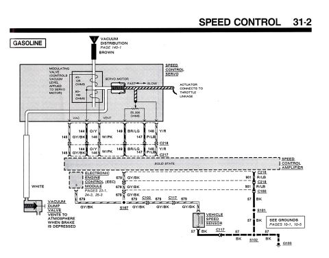
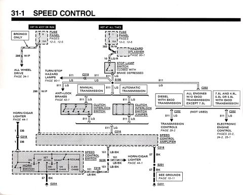



Ford speed control (cruise) wiring diagram page 31-2 showing the servo amplifier, modulating valve (40-125/60-190 ohm), servo motor, vacuum dump valve, EEC module and vehicle speed sensor with wire colors.
Part of 1987-1991 Ford Bronco Wiring Diagrams
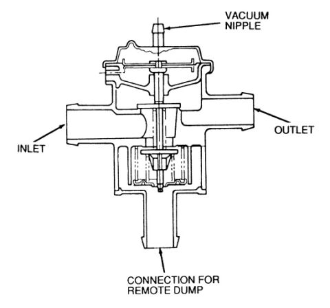
This document is page 31-2 of a Ford factory wiring diagram (EVTM-style) covering the Speed Control (cruise control) system for gasoline engines. It shows the speed control servo assembly, including the modulating valve (which controls vacuum level applied to the servo motor, with 40-125 ohm and 60-190 ohm windings), the servo motor with fast/slow actuation, an actuator that connects to the throttle linkage, and a 50,000-ohm feedback resistor. Vacuum is supplied from the vacuum distribution system (see page 140-1, brown hose), and a vacuum dump valve vents to atmosphere when the brake is depressed. Servo wiring passes through connectors C218 and C217 using circuits 144 O/Y, 145 GY/BK, 146 W/PK, 147 P/LB, 148 Y/R, and 149 BR/LG to the solid-state speed control amplifier. The amplifier connects to the Electronic Engine Control (EEC) module (pages 23-1, 24-3, 25-3) via circuit 679 GY/BK, which also runs through splice S167 and connectors C103 and C117 to the vehicle speed sensor. Power/signal circuit 901 R/LB passes through C216 and C218. Grounds run on circuit 57 BK through C100, S101, S102, C117, and ground G100 (see grounds pages 10-1 and 10-5).
Is this accurate? Sign in to help verify it.
Frequently asked questions
- What wire colors connect the speed control servo to the amplifier?
- Through connectors C218 and C217: circuit 144 O/Y, 145 GY/BK, 146 W/PK, 147 P/LB, 148 Y/R, and 149 BR/LG.
- What are the resistance specs for the speed control servo modulating valve?
- The diagram shows 40-125 ohms and 60-190 ohms for the modulating valve windings, plus a 50,000-ohm resistor in the servo circuit.
- What circuit connects the vehicle speed sensor to the speed control amplifier and EEC module?
- Circuit 679 GY/BK, which passes through splice S167 and connectors C103 and C117 to the vehicle speed sensor.
- What does the vacuum dump valve do in this speed control system?
- It vents vacuum to atmosphere when the brake is depressed, disengaging the cruise control.
- Where are the grounds for the speed control circuit?
- Ground circuit 57 BK runs through C100, splices S101 and S102, and connector C117 to ground G100; the diagram references grounds on pages 10-1 and 10-5.






No comments yet.