Home/
Registry/
Ford/
Mustang/
1964-1973/
1965 Ford Mustang/
Photo
supermotors.net/registry/media/508068
Driveshaft U-Joint Working Angle Diagram - 2° & 3° Driveline Angles (CAD)
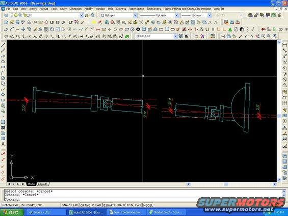
AutoCAD screenshot showing a dimensioned driveshaft engineering drawing with angle and diameter callouts.
This document is a screenshot of AutoCAD 2006 (file "Drawing2.dwg") showing a CAD blueprint of a two-piece driveshaft assembly, uploaded as "DS angle.JPG" to illustrate driveline/driveshaft working angles. The drawing shows two shaft sections drawn in cyan with red phantom centerlines, connected through what appear to be U-joint/slip-yoke assemblies, terminating at a large bell-shaped housing (differential or transmission end) on the right. Four angle callouts are dimensioned in red: 2.0° at the far left joint, 3.0° at each of the two center joints, and 2.0° at the far right joint. The screenshot also captures the standard AutoCAD interface: layer set to 0, ByLayer color/linetype, a text-style dropdown reading "ZRHD-LJH," the Model/Layout1 tabs, a command line showing "Select objects: *Cancel*" prompts, and a status bar with coordinates (6.747140E+00, 0'-6 27/64", 0'-0") and drafting toggles (SNAP, GRID, ORTHO, POLAR, OSNAP, OTRACK, DYN, LWT, MODEL). A reader can learn the intended operating angles at each driveshaft joint (2° at the ends, 3° at the center joints), useful for setting up or checking driveline geometry to minimize vibration. No vehicle year, make, model, or part numbers appear in the drawing itself.
Is this accurate? Sign in to help verify it.
Frequently asked questions
- What driveshaft angles are shown in this diagram?
- The diagram calls out 2.0° at the far left joint, 3.0° at each of the two center joints, and 2.0° at the far right joint.
- What software was this driveline angle drawing made in?
- AutoCAD 2006; the title bar shows 'AutoCAD 2006 - [Drawing2.dwg]'.
- How many joints/angle points are dimensioned in the drawing?
- Four angle callouts are dimensioned: two at 2.0° (the outer ends) and two at 3.0° (the center joints of the two-piece shaft).
- Does the drawing specify a vehicle year or model?
- No. The drawing contains only geometry and angle callouts; no year, make, model, or part numbers are visible.
Comments
More from this build
No comments yet.