Home/
Registry/
Ford/
Bronco/
1992-1996/
1993 Ford Bronco/
Photo
supermotors.net/registry/media/517497
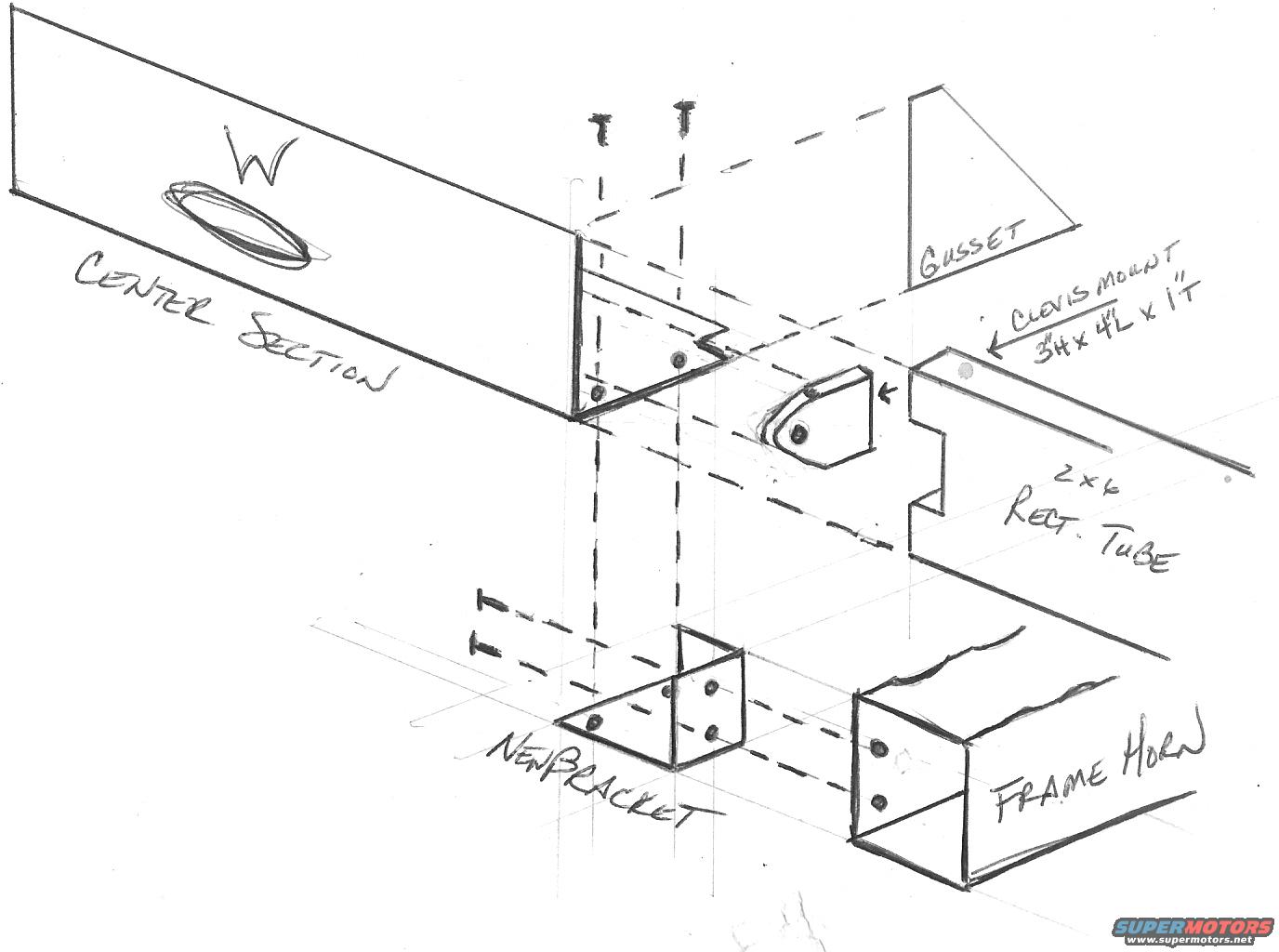
1993 Ford Bronco Custom Bumper Frame Mount Exploded Design Sketch - Clevis Mount
Reference · 1992-1996 BroncoAll 169 exploded parts diagrams
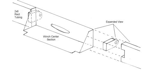
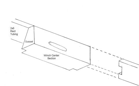
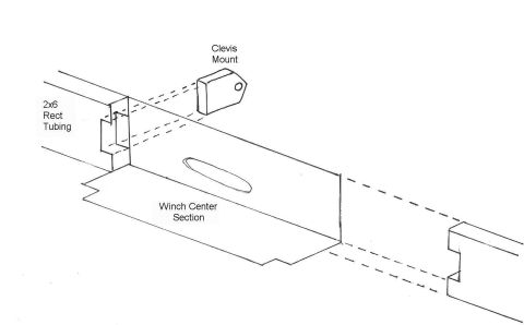
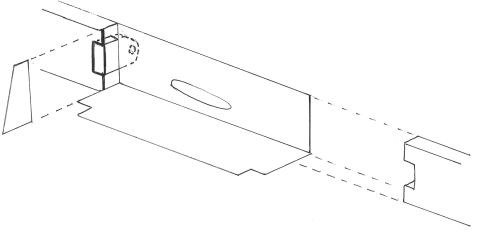
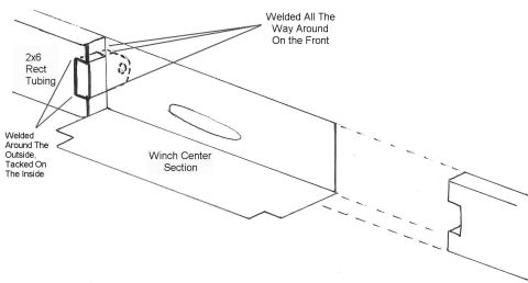
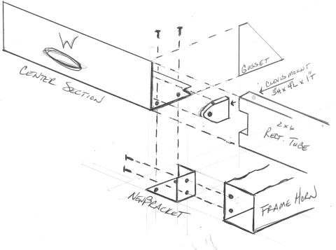
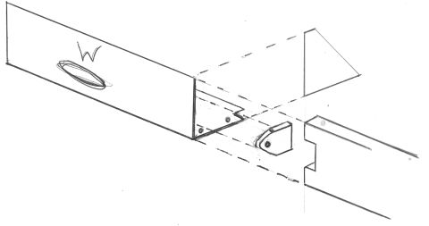

Hand-drawn assembly diagram labeling center section, gusset, clevis mount, rect tube, new bracket and frame horn with fit-up lines.
Part of 1992-1996 Ford Bronco Exploded Parts Diagrams
This document is a hand-drawn exploded design sketch showing a custom fabricated bumper/frame attachment assembly, uploaded to the gallery of a 1993 Ford Bronco. The isometric pencil drawing illustrates how several fabricated components fit together. The main components labeled are: a large "CENTER SECTION" (a channel or beam marked with a "W", featuring an oval cutout/slot), a triangular "GUSSET" plate, a "CLEVIS MOUNT" with dimensions noted as 3" high x 4" long x 1" thick, a "2 x 6 RECT. TUBE" (rectangular tubing) that slots into the center section, a "NEW BRACKET" (an angled bracket with bolt holes shown below the assembly), and the vehicle's "FRAME HORN" (the boxed frame end into which the rectangular tube and bracket bolt). Dashed lines with bolt symbols indicate fastener locations and alignment paths between the center section, the new bracket, the rectangular tube, and the frame horn. A reader can learn the general construction concept and assembly sequence of this custom front-end/recovery mount design, including where the gusset and clevis mount attach to the rectangular tube and how the assembly ties into the truck's frame horns. No year, model, part numbers, or torque values appear in the drawing itself.
Is this accurate? Sign in to help verify it.
Frequently asked questions
- What dimensions are given for the clevis mount in this design sketch?
- The clevis mount is labeled as 3" high x 4" long x 1" thick.
- What size tubing is used in this design?
- The drawing calls out a 2 x 6 rectangular tube ('2 x 6 RECT. TUBE') that slots into the center section and inserts toward the frame horn.
- What components are shown in this exploded design drawing?
- The labeled components are the center section, a gusset, a clevis mount (3"H x 4"L x 1"T), a 2x6 rectangular tube, a new bracket, and the frame horn.
- How does the assembly attach to the vehicle?
- Dashed alignment lines and bolt symbols show the new bracket and rectangular tube bolting to the vehicle's frame horn, with the center section mounting over them via additional bolts.


No comments yet.