Ball joint removal and installation instruction sheet, steps 13…
Reference · 1992-1996 BroncoAll 143 service procedures

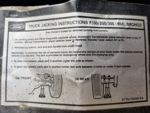







Ball joint replacement instructions using D-150-1, D-150-3 and D-150-4 tools with upper and lower nut torque steps. Sheet marked PCD 254 and 60-000050-100.
Part of 1992-1996 Ford Bronco Service Procedures
NOTE The above menlrened palts In slep 1T end T2 are nei shown in Fig T T3. Remove cutter key (R) lrern upper bail (eini siud (S). Leesen pain The upper (U) end lewer (V) bail icini siud nuis Te. Using a rewnlee hemmsl, enerely ti'lB ieese nur (U) on me 5m Di me upper bell )oint (S) in lree me lrnuc (O) irenr lire tuba yeke (W). Alier knuckle (O) is iree lrcm me yoke (W), remeue pern'llie upper (U) end lewer (V) nurs. Discald bomm nui (V). THE NUT ON THE LDWEFI BALL JOINT (T) is OF THE TOROUE PREVAILING DESIGN AND ls NOTTOBE REUBED. . Remove threaded sleeve (x) irum yuke (W) wiin Tuel Nu. OATss seckei eieenng arm (Rel. Siep 12) ll lower eeIl icini is equipped wlin e snap ring M, remeve l1 NOTE BE SURE THAT VISE JAWS ARE EOUIPPED wrn-I BRASS PROTECTORS OFI SIMILAR TVPE To PROTECTTI-E MACHINED SURFACE OF ANY PARTS THAT ARE TO BE PLACED IN THE VISE. ATTENTION: LOWER BALL JOINT MUST BE REMOVED BEFORE THE TOP BALL JOINT CAN BE REMOVED. WE RECOMMEND BOTH UPPER AND LOWER BALL JOINTS BE REPLACED As PAlel T7. Lewer bell Tuini (T) in removed by piecing seckel end el toei (D isn l) wiih sleeve (in 15M) ineeried ever eiud ul Iuwer bell juin! (T). Piece edepier (D 15H) egeinsi eeuem el bell (mini 0] (Oppeslie sine and) end iurn ediueIJng screw ei nex e'nd of loci (D4504) ti: engege hale ei edepier (D-isorz). Keep turning edlusimenl screw iill bell juini (T) Is rerneved. 18. Remove luel (D 150 I) and bell jalnt _ Wises-sleeve (:5 . (e. lneen edluslmeni schw (Hex End) el oul (D 1501) inreugn iewer bell (oini (r) DpBrT'Ing in knuckle (O). 20. REPEAT STEP N0. 17. ONLY PERFORM D To UPPER BALL JOINT (3). 2| Remeve leel (D-Tso T) end bBIl'j nl (S) nm sleeve (D ism) ASSEMBLY: NEw LOWER BALL JOINT MUST BE INSTALLED BEFORE THE UPPER BALL JOINT CAN BE INSTALLED. 22Teke an Tower bell ieinl (T) (Nu cellar pin l'mie ln 5de 3,5" lass!" Its base {7 1 id;- Three" eu-rknuckle ie, .lniu lis War rail 1 ml rule. may "9 sure mull line em. on . eedy is weigh? with ma ngre. slrike * kr Mme(crux We..." 23. The new lewer hall jam! (T) can new be Inslniled by Iakln'g lne ieul (D4504) end . insenine me nex grid el iis adjusling screw inrcueh me Raisin lhe knuckle Ier ine upper bail leinL . 24. lnseri sleeve (0-1504) inie the socke: and pi the lee! (D-Tsn-T) end . slreedle lire Ie'wer bell jelni hele epening. Teke sleeve (0-1504 and slide The large upening and ever I 'new laws: bail jainl (T) slucl end engage llenge ol me 'ueil jelni Tum adjusling screw (Hex End) ei reel '(Dr150-1) le engege".smell pilot hole in sleeve (D-iso- 4) and keep [may ex hex end el ediusirnent screw lill eel) ieini (T) is lnsislled. 25. Remeve ieul (Disc-T) eneeleeves (D1503 and D150 4) (ram rne nsreiled iewer bell (aim and me knuckle. 26. ll re Uired assemble snap ring en WW 27 Teke new upper bell jalm (S) (ern ( cwllal pin nele in siud) end insert (Is eese 1 Train die cuiside Bf rne knuckle (O) lnl iis uppereell pin! (rule. making sure rnei me 3 eeli jmrlt eddy is sireignl wlin the lime. NEWUPPEHBALLJOINT(S). Remeve leel (D4504) end sleeves 'upgnl pull (elm end The Knuckle. Make sure hall jeini exude end seele ere iree (rem dirL em. 1 Remeve knuekle wilh essemeled eeil jninls (rum V459 32 Assemble knuckle (0) will) usil )uinls Inie essempied yoke (w). neles es pesrliened drieinelly. 33 Ass blo new rereue evevelline nui en ' lewer View siud iinai Ii M. Assemble .4 upper nui an upper bail icini. DO NOT ASSEMBLE AT THISTIME Tnlqua upper nul unni ix is dam. This will pull me siud al The eenpm seckei inle me epered nele 01 me yukei TOROUE LOWER NUT To so new assemble new hreeded sleeve ()0 interim), el yeke. Unlmjssieeve sockntmoi Na. 5 4169 and minus Wmnch OROUE SLEEVE To 5e lbs. (L . 7 35. Assemble ubpel bell )Birll nut. TOROUE UPPER NUT To Tag lbs lL Aner nuLhBS been icrduee gghmn niil In line up (he eener ikey elrsv el ine smd with me next cesxelleiion er slel ei ills nur. DO NOT LOOSENNUT, as. Amele. r key to upper hall (dint Stud. 7 37. In re eree order reassemble pens in siepe Nu.12ihvu No l as. Heve vehicles. checked. wheel Vallnnmant 1Q 'REPEAT STEP NO. 24. ONLY PERFORM IT_ 3) end (DISU-fc) (mm lhe Installed- We
Is this accurate? Sign in to help verify it.






No comments yet.