SuperMotors SuperMotors SUPERMOTORS Search: try “orange Bronco on 35s”
Home/ Registry/ Ford/ Bronco/ 1992-1996/ “Shadofax”/ Photo supermotors.net/registry/media/832372

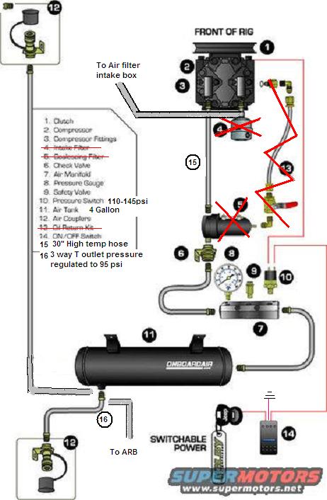
On-Board Air (OBA) System Schematic - 1995 Ford Bronco Compressor & Tank Layout

Onboard air compressor plumbing schematic with numbered legend
Onboard air compressor plumbing schematic with numbered legendOriginal file
Onboard air compressor plumbing schematic with numbered legend

Reference · 1992-1996 BroncoAll 95 schematics
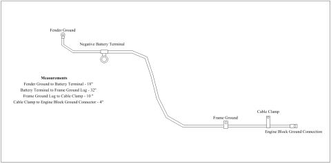
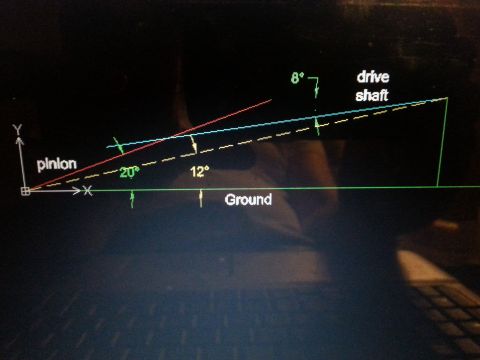
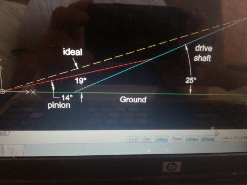
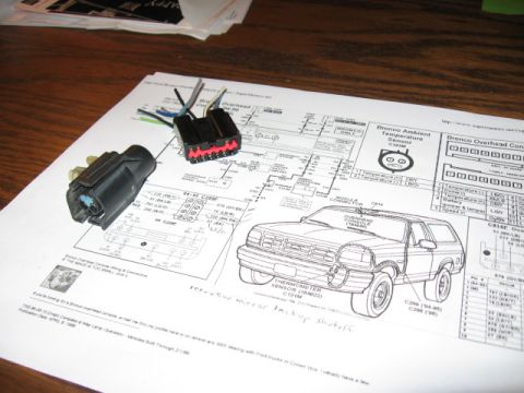
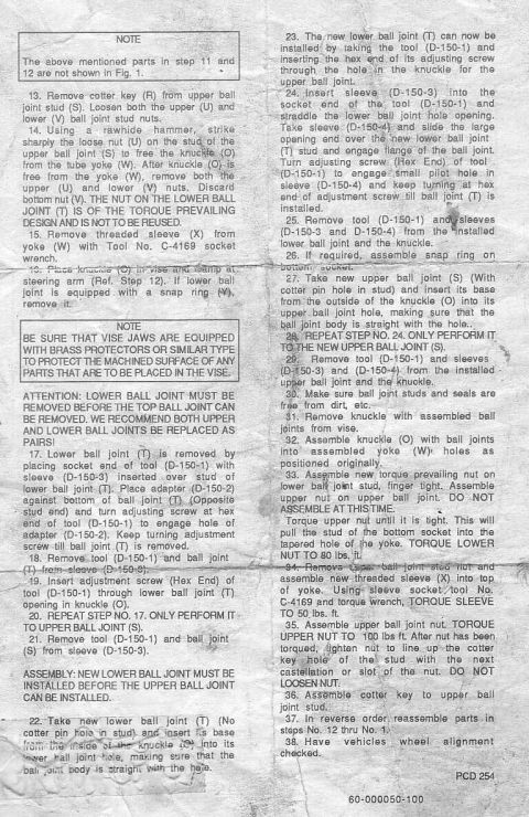
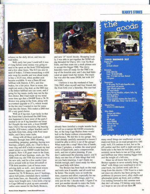
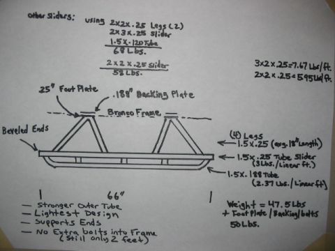
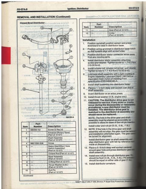
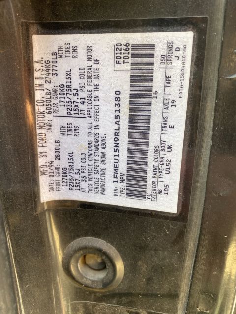
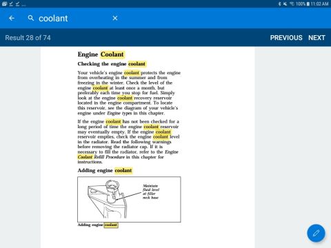
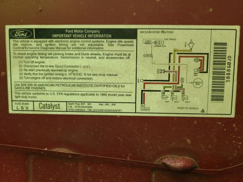
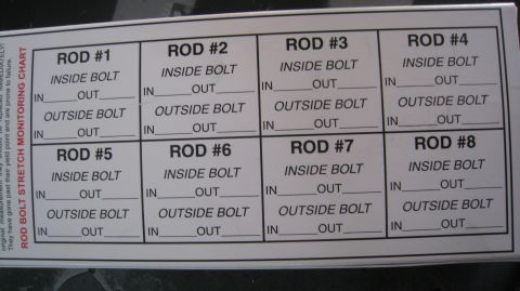
On-Board Air (OBA) System Schematic - 1995 Ford Bronco Compressor & Tank Layout 1993 Ford V8 Serpentine Belt Routing Diagram - Pulley Layout (Q2601-E) Ford 5.0 Serpentine Belt Routing Diagram - Factory & Smog Pump Bypass Belt Sizes 1996 Ford Bronco 5.0L & 5.8L Serpentine Belt Routing Diagram (F6TE-8B656-AA) Caster Angle Diagram - Ford Solid Axle Radius Arm & C-Bushing Steering Geometry Ford 5.0L / 5.8L HO Firing Order Diagram - Spark Plug Wire Routing & Timing 1994 Ford Bronco Negative Battery Cable Diagram - Ground Cable Lengths 1996 Ford Bronco EVTM 151-1 Component Location Views - 5.0L/5.8L Engine Bay 1994 Ford Bronco/F-150 EVTM 151-15 Component Location Views - Behind Dash 1994 Ford Bronco Negative Battery Cable Diagram - Ground Cable Measurements Driveshaft & Pinion Angle Diagram - 20°/12° Ground Angles, 8° U-Joint Angle Driveshaft & Pinion Angle CAD Diagram - 14° Pinion, 25° Driveshaft (Ford Bronco) 95schematics1992-1996 Ford Bronco More reference 1994-1996 Ford Bronco Overhead Console Wiring Diagram - Connectors & SensorWiring diagram Ball joint removal and installation instruction sheet, steps 13 through 38, using D-150 tool setService procedure Bronco Driver Reader's Stories page on a 1995 Bronco XLT solid axle swap with The Goods spec sidebarBrochure Ford Bronco Rock Slider Blueprint - Tube Sizes, Weights & Frame Mount DesignBlueprint 1996 Ford Bronco/F-150 Distributor Exploded Parts Diagram & Installation 03-07A-6Exploded parts 1994 Ford Bronco Door Data Spec Plate - VIN, GVWR, Axle & Paint CodesSpec plate 1996 Ford Bronco Owner's Manual - Checking & Adding Engine CoolantManual page 1995 Ford Bronco 5.8L Emissions/VECI Label - Vacuum Hose Routing DiagramVacuum routing Ford Bronco/F-Series Fuse 18 (10A) - Speedometer, Air Bag, Shift ControlFuse chart Rod Bolt Stretch Monitoring Chart - 8-Rod V8 Connecting Rod Bolt Record SheetTorque spec

Schematic of an onboard air system showing compressor, air tank, hoses and gauges with a numbered component legend.

Part of 1992-1996 Ford Bronco Schematics

AI caption · Photo 816 of 1128

This document is an annotated schematic of an on-board air (OBA) system, uploaded to a 1995 Ford Bronco gallery. It shows a belt-driven air compressor with clutch mounted at the front of the rig, plumbed through compressor fittings and a 30-inch high-temperature hose to a check valve, then into an air manifold. The manifold carries a pressure gauge, safety valve, and a pressure switch rated 110-145 psi. Air is stored in a 4-gallon ONBOARDAIR tank, which feeds air couplers at both the front and rear of the vehicle. A numbered legend identifies 16 components; three items, the intake filter, coalescing filter, and oil return kit, are crossed out in both the legend and diagram (marked with red X's), indicating they were deleted from this builder's setup. Instead, the compressor intake is routed to the factory air filter intake box. Item 16 is a 3-way T outlet with pressure regulated to 95 psi that supplies an ARB (air locker). Electrical control is via an ON/OFF switch connected to switchable power. A reader can learn the component layout, plumbing order, pressure switch and regulator settings, tank size, and which kit components this owner omitted.

Is this accurate? Sign in to help verify it.

Frequently asked questions

What pressure range is the pressure switch set to in this on-board air schematic?
The pressure switch (item 10) is labeled 110-145 psi.
How big is the air tank in this OBA setup?
The air tank (item 11) is a 4 gallon ONBOARDAIR tank.
Which components are deleted (crossed out) in this schematic?
The intake filter (4), coalescing filter (5), and oil return kit (13) are crossed out. The compressor intake is instead routed to the air filter intake box.
What pressure feeds the ARB in this setup?
Item 16 is a 3-way T outlet with pressure regulated to 95 psi, with a line labeled 'To ARB'.
What length and type of hose connects the compressor?
Item 15 is a 30-inch high temp hose.
Comments

No comments yet.

More 1992-1996 Broncos