SuperMotors SuperMotors SUPERMOTORS Search: try “orange Bronco on 35s”
Home/ Registry/ Ford/ Bronco/ 1980-1986/ “The Mall-Crawler”/ Photo supermotors.net/registry/media/531830

Edelbrock Performer 5.8 lower intake manifold with labeled EGR p…

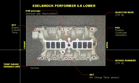
Edelbrock Performer 5.8 lower intake manifold with labeled EGR passage, injector bosses, PCV and sensor ports
Edelbrock Performer 5.8 lower intake manifold with labeled EGR passage, injector bosses, PCV and sensor portsOriginal file
Edelbrock Performer 5.8 lower intake manifold with labeled EGR passage, injector bosses, PCV and sensor ports

Reference · 1980-1986 BroncoAll 34 schematics
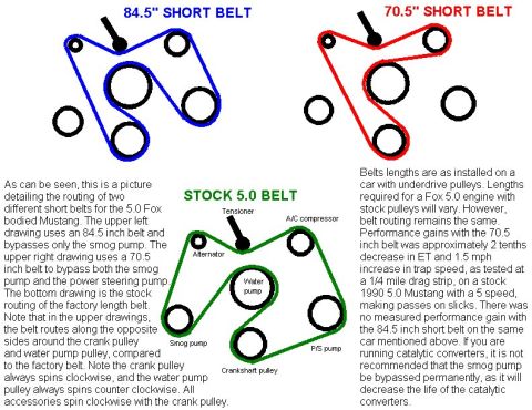
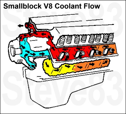
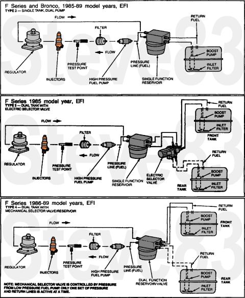
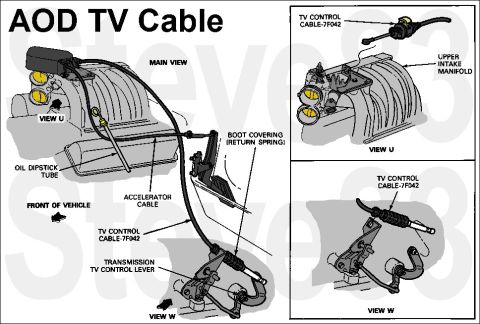
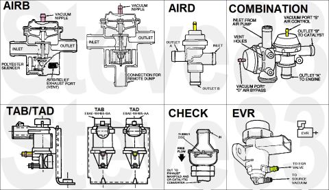
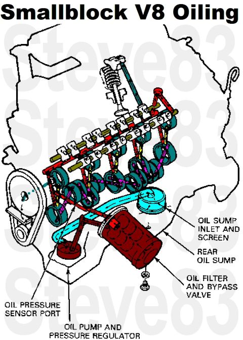
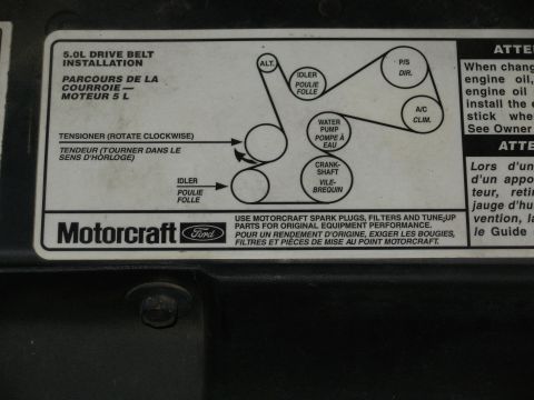
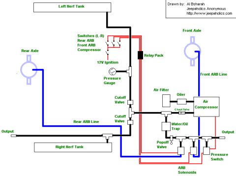
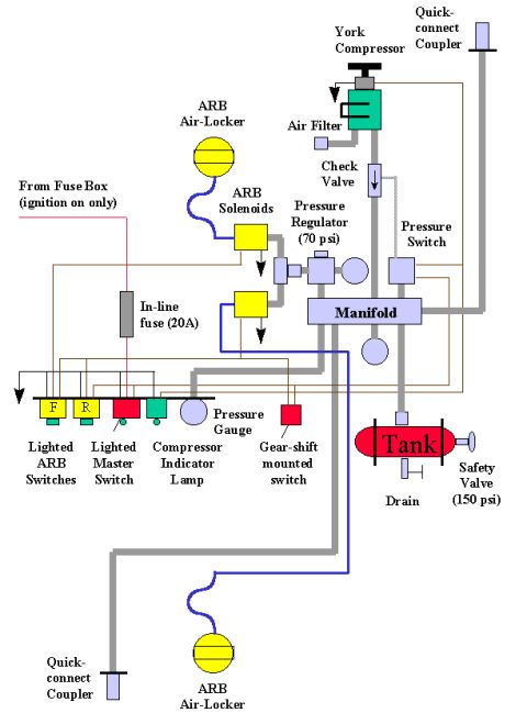
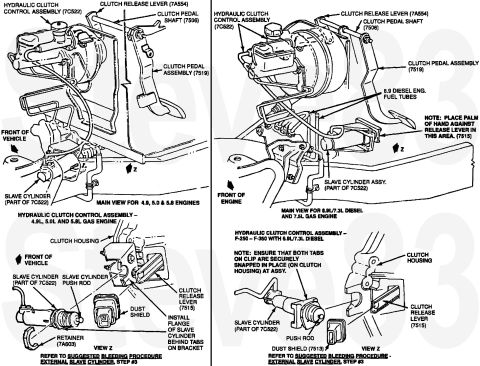
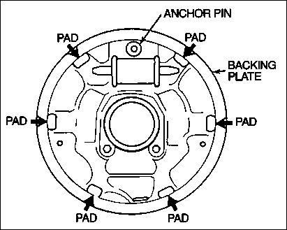
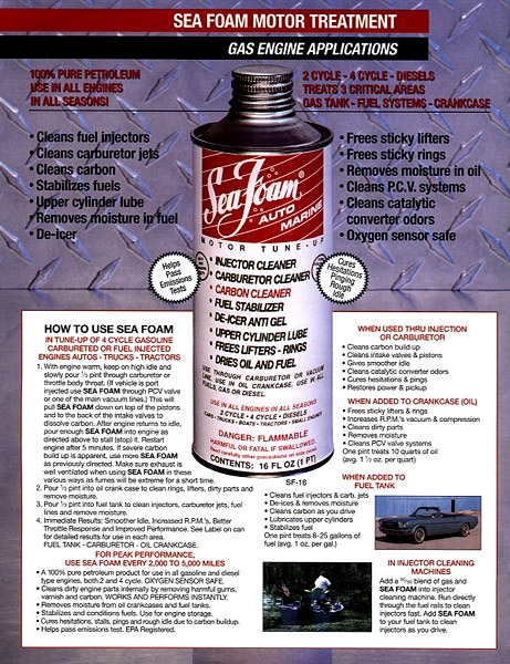
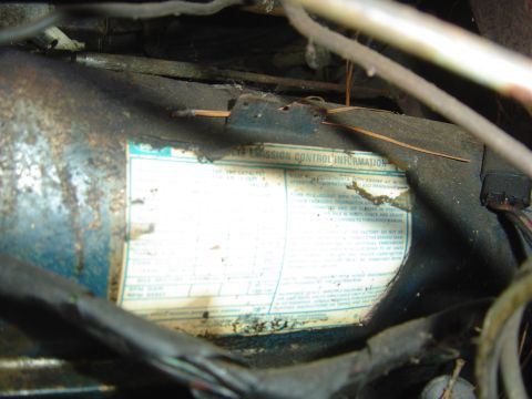
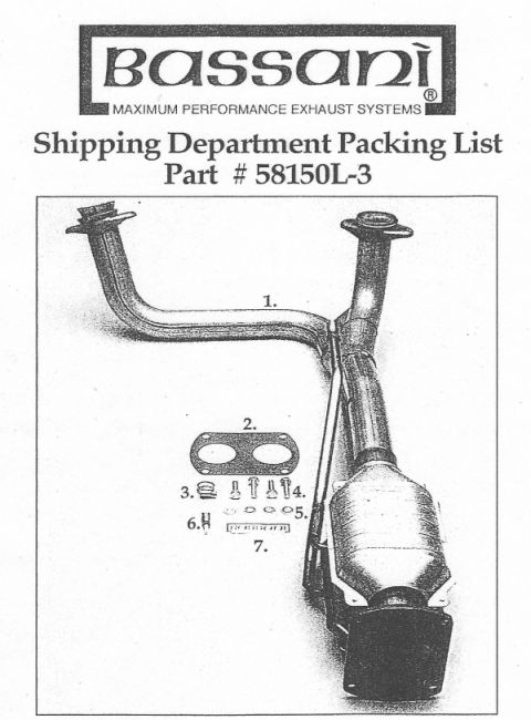
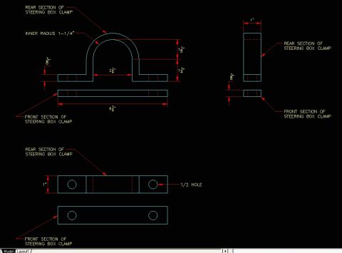
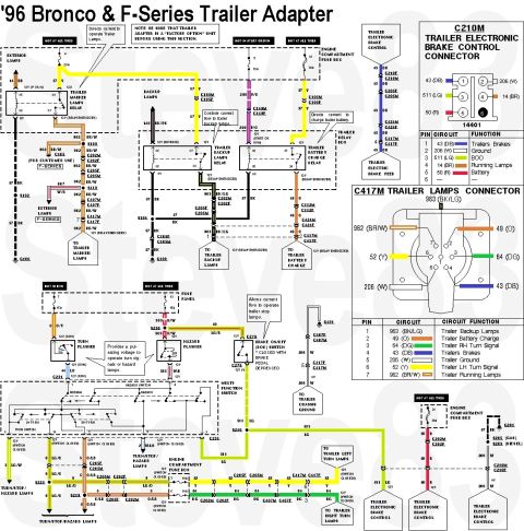
Fox Body Mustang 5.0 Serpentine Belt Routing Diagram - Stock & Short Belts Edelbrock Performer 5.8 lower intake manifold with labeled EGR passage, injector bosses, PCV and sensor ports Smallblock V8 Coolant Flow Diagram - Ford Engine Cooling Path Schematic 1985-89 Ford F-Series & Bronco EFI Fuel System Diagrams - Single & Dual Tank Ford AOD Transmission TV Cable Routing Diagram - 7F042 Cable & Lever Views Ford Thermactor Secondary Air Valves Diagram - AIRB AIRD TAB TAD EVR Check Valve Smallblock V8 oiling diagram with oil pump, filter, sump and pressure passages Ford 5.0L Serpentine Drive Belt Routing Diagram - Motorcraft Underhood Decal On-Board Air (OBA) & ARB Air Locker System Schematic - Compressor Wiring Diagram On-Board Air System Schematic - York Compressor & ARB Air-Locker Wiring Diagram Ford Truck Hydraulic Clutch (7C522) Slave Cylinder Diagram - Gas & Diesel Ford Bronco Drum Brake Backing Plate Diagram - Shoe Pad & Anchor Pin Locations 34schematics1980-1986 Ford Bronco More reference Sea Foam Motor Treatment gas engine applications sheet with product can, benefits list and usage directionsBrochure Weathered Ford vehicle emission control information label on air cleaner, mostly illegibleSpec plate Bassani packing list for part # 58150L-3 Y-pipe with catalytic converter and numbered hardwareExploded parts Ford AOD 3-4 Shift Valve & Governor Limit Valve Install - Shift Kit InstructionsService procedure Ford Bronco Steering Box Clamp Brace Blueprint - Dimensions & Fab DrawingBlueprint 1996 Ford Bronco & F-Series Trailer Wiring Diagram - 7-Pin Connector PinoutWiring diagram 1996 Ford Bronco/F-Series Starting System - Section 03-06 ContentsManual page 1985 Ford Bronco Vacuum Hose Routing Diagram - EGR, TAB/TAD Solenoids, CanisterVacuum routing Bronco drive shaft torque limits table and special tool T74P-4635-CTorque spec '95 F150 fuse and relay chart with fuse panel layout, ATC and Maxi fuse amp tablesFuse chart

Edelbrock Performer 5.8 lower intake manifold labeled with EGR passage, injector bosses, intake runners, PCV, ECT, ACT and temp gauge sending unit ports.

Part of 1980-1986 Ford Bronco Schematics

AI caption · Photo 479 of 940

F EGR plunge (exhuu qcls resurcmuuon) Coomm Positive Temp Crunkcclse Venmaan Gucknclr .12:v (Air Charge Temp sensor)

Is this accurate? Sign in to help verify it.
Comments

No comments yet.

More 1980-1986 Broncos