Home/
Registry/
Ford/
Bronco/
1980-1986/
1986 Ford Bronco/
Photo
supermotors.net/registry/media/768342
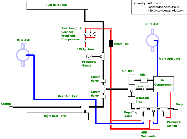
On-Board Air (OBA) & ARB Air Locker System Schematic - Compressor Wiring Diagram
Reference · 1980-1986 BroncoAll 34 schematics
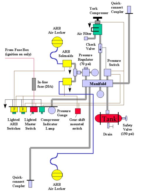

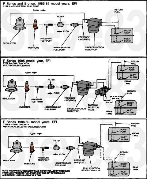
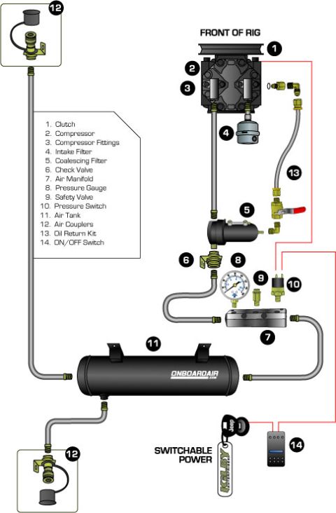





Schematic of an ARB onboard air system showing compressor, cutoff valves, pressure switch, solenoids, and air-line routing to the axles.
Part of 1980-1986 Ford Bronco Schematics
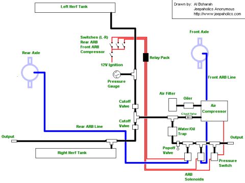
This document is a hand-drawn schematic (by Al Bsharah of Jeepaholics Anonymous, http://www.jeepaholics.com) showing the layout of an on-board air (OBA) system integrated with ARB air lockers. The diagram illustrates both the air plumbing and electrical wiring for the system. Air components include an air compressor with an inline air filter, oiler, and check valve; a water/oil trap; a popoff (pressure relief) valve; a pressure switch; and two air storage tanks built into the vehicle's nerf bars (labeled Left Nerf Tank and Right Nerf Tank), each with an output port. Air lines (shown in blue) run to the front and rear axles via Front ARB Line and Rear ARB Line, each controlled by an ARB solenoid and an inline cutoff valve. A pressure gauge monitors system pressure. Electrically (shown in red), three dash switches (left to right: Rear ARB, Front ARB, Compressor) are fed by 12V ignition power and control a relay pack that operates the compressor and the ARB solenoids. A reader can learn the component order for plumbing (compressor → oiler → check valve → trap → tanks/lockers) and how to wire switches through relays for compressor and locker control. No specific vehicle year, make, model, or part numbers are stated.
Is this accurate? Sign in to help verify it.
Frequently asked questions
- What is the switch order on the dash in this on-board air schematic?
- The three switches are labeled left to right: Rear ARB, Front ARB, and Compressor, powered from 12V ignition and wired through a relay pack.
- Where is compressed air stored in this system?
- In two nerf bar tanks, the Left Nerf Tank and Right Nerf Tank, each with an output port.
- What components are plumbed with the air compressor?
- The compressor connects to an air filter and an oiler, with a check valve on its output, followed by a water/oil trap, popoff valve, and pressure switch.
- How are the ARB air lockers controlled?
- ARB solenoids feed the Front ARB Line and Rear ARB Line to the front and rear axles, each line with its own cutoff valve; the solenoids are switched via the relay pack from the dash switches.
- Who drew this schematic?
- It was drawn by Al Bsharah of Jeepaholics Anonymous (http://www.jeepaholics.com).






No comments yet.