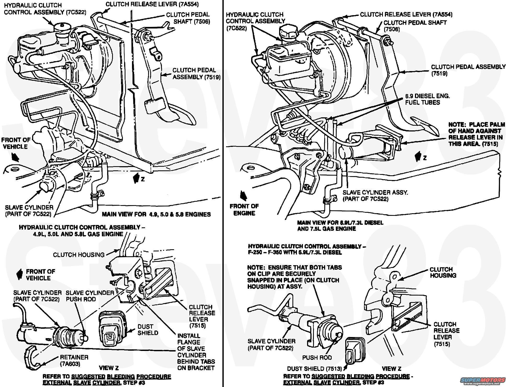
Ford Truck Hydraulic Clutch (7C522) Slave Cylinder Diagram - Gas & Diesel
Reference · 1980-1986 BroncoAll 34 schematics
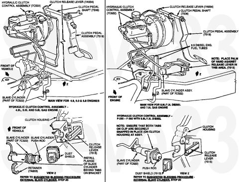






Suggested Bleeding Procedure - External Slave Cylinder
If the truck is a 1987 or prior model, 1988 model with a 7.3L Diesel, 7.5L EFI gas engine or the smaller family of engines with a Warner T-18 four speed transmission, proceed as follows:
1. Remove the master cylinder reservoir cap and diaphragm.
2. Check the fluid level to be sure it is at the step diameter of the reservoir. Do not over fill.
3. From below the truck, push the release lever slowly towards the front of the truck several times. Figures 11 & 12.
4. If it will not move, the master cylinder pushrod is not set correctly. See repair Step # 19.
5. Check the fluid level, then replace the diaphragm and cap.
Suggested Bleeding Proc - Internal Concentric Slave CYL.
If the truck has a concentric slave cylinder, proceed as follows:
1. Operate the clutch pedal at full stroke, 10-20 times.
2. Check the fluid level at the change in diameter part of the reservoir. Do not over fill.
3. Have an assistant depress the clutch pedal slowly and hold it down.
4. Open the slave cylinder bleed screw until air has escaped.
5. Close the bleed screw and have the assistant release pedal.
6. Repeat this cycle from step 3 several times until there is no sign of air. Be sure to keep the reservoir topped to the correct level.
7. Replace the diaphragm and reservoir cover.
8. Operate the clutch pedal at full stroke 10-20 times.
____________________________________________________
See also: .
.  .
.  .
. 
Part of 1980-1986 Ford Bronco Schematics
Is this accurate? Sign in to help verify it.
Frequently asked questions
- What Ford part number is the hydraulic clutch control assembly?
- The hydraulic clutch control assembly is identified as part reference 7C522; the slave cylinder is part of the 7C522 assembly.
- Which engines does this clutch diagram cover?
- It shows a main view for 4.9L, 5.0L and 5.8L gas engines, and a second main view for 6.9L/7.3L diesel and 7.5L gas engines (F-250: F-350 with 6.9L/7.3L diesel).
- How is the external slave cylinder installed on the gas-engine trucks?
- View Z shows that the flange of the slave cylinder must be installed behind the tabs on the bracket, with the push rod, dust shield, and retainer (7A603) in place.
- What assembly note applies to the diesel clutch housing clip?
- The note states to ensure that both tabs on the clip are securely snapped in place on the clutch housing at assembly.
- Where does the diagram say to bleed the system?
- Both views refer the reader to the 'Suggested Bleeding Procedure - External Slave Cylinder, Step #3.'






No comments yet.