Home/
Registry/
Ford/
Bronco/
1980-1986/
1986 Ford Bronco/
Photo
supermotors.net/registry/media/768341
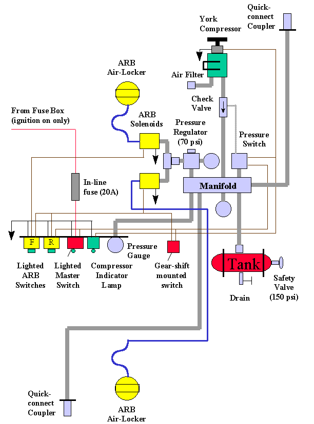
On-Board Air System Schematic - York Compressor & ARB Air-Locker Wiring Diagram
Reference · 1980-1986 BroncoAll 34 schematics
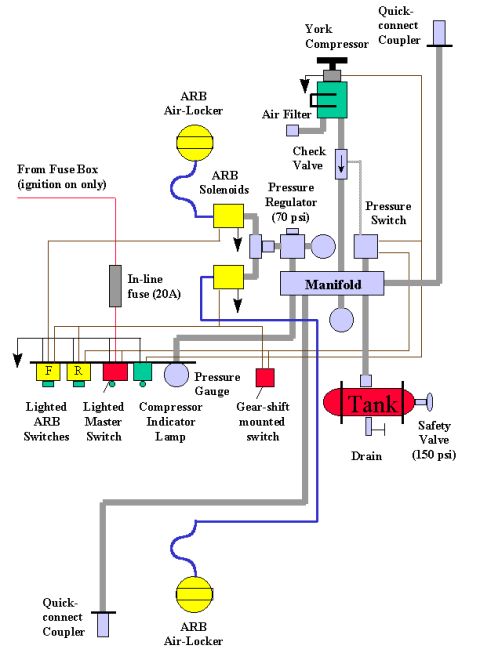

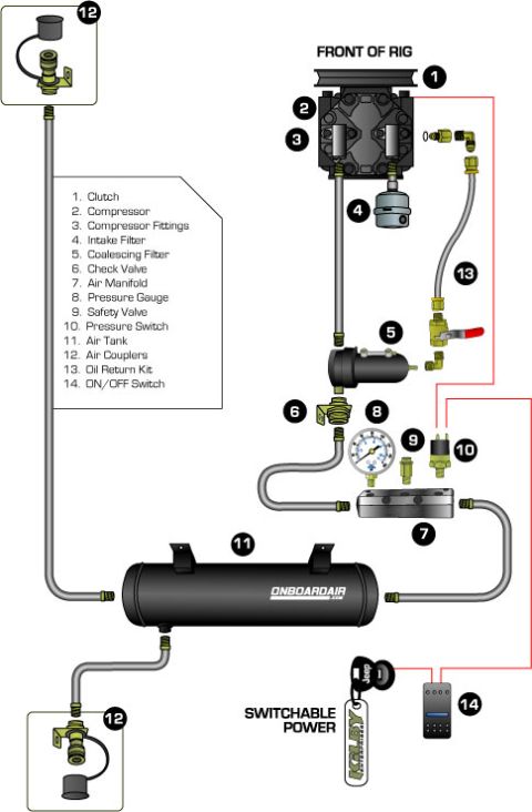






Plumbing schematic for an ARB Air-Locker on-board air setup: York compressor through check valve, 70 psi pressure regulator, manifold, tank, ARB solenoids and lighted dash switches, fed from a 20A in-line fuse.
Part of 1980-1986 Ford Bronco Schematics
This document is a color schematic diagram for an on-board air (OBA) system built around a York compressor, combined with ARB Air-Locker differential controls. It shows the plumbing and electrical layout: the York compressor draws through an air filter and feeds through a check valve to a manifold, which connects to a pressure switch, a pressure regulator set to 70 psi, an air tank equipped with a drain and a 150 psi safety valve, a pressure gauge, and quick-connect couplers at the front and rear of the vehicle. Two ARB solenoids supply air from the regulator to the front and rear ARB Air-Lockers. Electrically, power comes from the fuse box (ignition-on only) through a 20A in-line fuse to a lighted master switch, two lighted ARB switches (labeled F and R for front and rear), a compressor indicator lamp, and a gear-shift mounted switch. A reader can learn the overall component arrangement, air-line routing, pressure setpoints (70 psi regulator, 150 psi safety valve), fuse rating (20A), and how the switches, solenoids, and lockers interconnect in a typical DIY on-board air / air-locker installation.
Is this accurate? Sign in to help verify it.
Frequently asked questions
- What pressure is the regulator set to in this on-board air system?
- The pressure regulator is set to 70 psi, feeding the ARB solenoids for the Air-Lockers.
- What size in-line fuse does this OBA schematic use?
- A 20A in-line fuse, fed from the fuse box on an ignition-on-only circuit.
- What safety devices are shown on the air tank?
- The tank has a drain and a safety valve rated at 150 psi.
- What switches control the ARB Air-Lockers in this diagram?
- A lighted master switch and two lighted ARB switches labeled F and R (front and rear), plus a gear-shift mounted switch and a compressor indicator lamp.
- How does the compressor connect to the rest of the system?
- The York compressor draws through an air filter and feeds through a check valve into a manifold, which connects to the pressure switch, pressure regulator, pressure gauge, tank, and quick-connect couplers.






No comments yet.