Home/
Registry/
Ford/
Bronco/
1992-1996/
1994 Ford Bronco/
Photo
supermotors.net/registry/media/542774
Carburetor Exploded Parts Diagram - Numbered Callouts with Missing Parts Marked

Reference · 1992-1996 BroncoAll 169 exploded parts diagrams






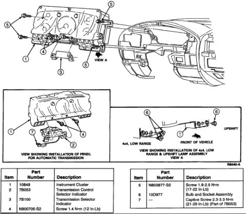
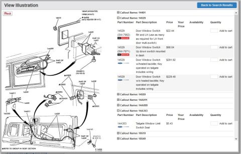
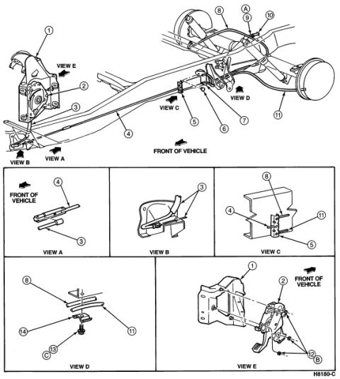
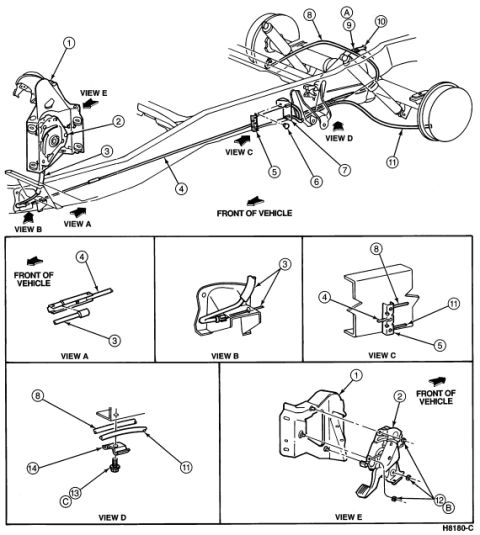
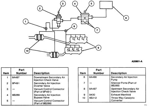









Exploded-view parts breakdown of a carburetor assembly with numbered callouts for each component.
Part of 1992-1996 Ford Bronco Exploded Parts Diagrams
This document is a scanned exploded parts diagram of a carburetor assembly. It contains no written part numbers, legend table, model identification, or dates, only numbered callouts (1 through 22, with several numbers not present or repeated) pointing to individual components of the carburetor. The illustration shows the carburetor body, top cap and slide assembly, jets and mixture screws, throttle linkage, float, float bowl, drain screw, and various vent/overflow hoses and fasteners. Two callouts are highlighted with red boxes, a boxed "1" near item 5 (in the jet/screw area on the left side of the carburetor body) and item 14 (a small clip or fitting near the float), consistent with the upload filename "parts missing.jpg," suggesting the uploader marked these as the missing parts. Without a legend or accompanying parts list, the reader can identify the relative position and assembly order of components by number but cannot determine part names or part numbers from this page alone. A companion scan ("carb.jpg") in the same album may contain the corresponding legend. The diagram style resembles a motorcycle/small-engine carburetor parts fiche rather than a typical full-size truck reference.
Is this accurate? Sign in to help verify it.
Frequently asked questions
- What does this diagram show?
- An exploded view of a carburetor assembly with numbered callouts (1-22) identifying individual components such as the body, top cap, jets, float, float bowl, throttle linkage, hoses, and fasteners.
- Which parts are highlighted as missing?
- Two callouts are marked with red boxes: a boxed "1" near item 5 in the jet/screw area on the left side of the carburetor, and item 14, a small clip/fitting near the float area.
- Does the diagram include part numbers or a parts legend?
- No. Only the numeric callouts are visible; there is no legend, part number list, or descriptive text on this page.
- What callout numbers appear on the diagram?
- Numbers 1, 2, 3, 5, 7, 8, 9, 10, 12, 13, 14, 15, 16, 17, 18, 19, 20, 21, and 22 are visible; some (like 1 and 21) appear more than once.






No comments yet.