SuperMotors SuperMotors SUPERMOTORS Search: try “orange Bronco on 35s”
Home/ Registry/ Ford/ Bronco/ 1992-1996/ 1994 Ford Bronco/ Photo supermotors.net/registry/media/542842

Carburetor Exploded View - Jet Needle, Slow Jet, Main Jet & Pilot Screw ID

Carburetor parts breakdown labeling throttle stop screw, jets, needle and pilot screw
Carburetor parts breakdown labeling throttle stop screw, jets, needle and pilot screwOriginal file
Carburetor parts breakdown labeling throttle stop screw, jets, needle and pilot screw

Reference · 1992-1996 BroncoAll 169 exploded parts diagrams

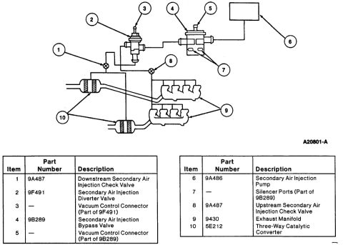
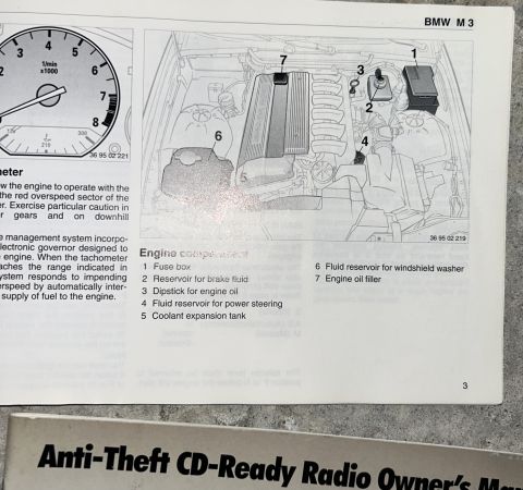
Carburetor Exploded View - Jet Needle, Slow Jet, Main Jet & Pilot Screw ID Carburetor Exploded Parts Diagram - Numbered Callouts with Missing Parts Marked Carburetor exploded parts diagram with numbered callouts for float bowl, slide, needle and jets 1996 Ford Bronco/F-150 Distributor Exploded Parts Diagram & Installation 03-07A-6 Ford Bronco Front Coil Spring & Shock Absorber Exploded Diagram (F2858-Q) Ford Bronco/F-Series Engine Block Ground Cable Diagram - Neg Battery Cable Views Instrument panel 04320 exploded view with finish panel 044D70, headlamp switch knob 11666 and mouldings Instrument cluster installation with PRNDL indicator, 4x4 low range and upshift lamp views and parts table Ford Bronco Tailgate Window Switch & Wiring Harness Parts Diagram - 14529, 14A353 1994 Ford Bronco Parking Brake Cable Diagram - E-Brake Routing & Exploded Views 1994 Ford Bronco Parking Brake Cable Routing Diagram - E-Brake Exploded View Ford Bronco Secondary Air Injection System Diagram - Smog Pump Parts & Layout 169exploded parts diagrams1992-1996 Ford Bronco More reference 1996 Ford Bronco C202F 76-Pin Connector Pinout - EVTM Page 150-4Wiring diagram Ford EEC-IV Output State Check & Cylinder Balance Test - Code Reader ProcedureService procedure 1994 Ford Bronco Door Data Spec Plate - VIN, GVWR, Axle & Paint CodesSpec plate BMW M3 Owner's Manual Page 3 - Engine Compartment Component LocationsManual page 1993 Ford V8 Serpentine Belt Routing Diagram - Pulley Layout (Q2601-E)Schematic Brake Booster to Master Cylinder Adapter Plate Blueprint - Ford Bronco SwapBlueprint 1994-1995 BMW 3 Series Owner's Manual Booklet Set - Warranty, Radio & AccessoriesBrochure 1995 Ford Bronco 5.8L Emissions/VECI Label - Vacuum Hose Routing DiagramVacuum routing Ford Bronco/F-Series Fuse 18 (10A) - Speedometer, Air Bag, Shift ControlFuse chart Rod Bolt Stretch Monitoring Chart - 8-Rod V8 Connecting Rod Bolt Record SheetTorque spec

Carburetor exploded parts illustration labeling throttle stop screw, spring, pilot screw, jets and needle.

Part of 1992-1996 Ford Bronco Exploded Parts Diagrams

AI caption · Photo 91 of 91

This document is a labeled photograph showing a carburetor partially disassembled, with its small metering and adjustment components removed and laid out beside the carburetor body. Arrows connect seven callout labels to the individual parts. The identified components are: the throttle stop screw (shown at the lower left of the carburetor body), the spring and pilot screw (upper right, with the spring shown next to a small O-ring), and along the lower right, the jet needle set, slow jet, needle jet holder, and main jet. The image serves as a visual parts-identification reference for anyone disassembling, cleaning, or rebuilding this style of carburetor, showing what each removable jet and screw looks like and its relative position when removed. No part numbers, torque specifications, jet sizes, adjustment settings, or vehicle/engine applicability information appear anywhere in the image, it is purely a component identification photo. The document itself contains no year, make, or model text, so its exact application cannot be confirmed from the image alone.

Is this accurate? Sign in to help verify it.

Frequently asked questions

What carburetor parts are identified in this exploded photo?
Seven parts are labeled: throttle stop screw, spring, pilot screw, jet needle set, slow jet, needle jet holder, and main jet.
Where is the pilot screw shown in the photo?
The pilot screw is shown at the upper right of the carburetor body, laid out next to its spring.
Does this document list jet sizes or adjustment specifications?
No. The image only labels the parts visually; no jet sizes, part numbers, or adjustment settings are given.
Which jets are shown removed from the carburetor?
The slow jet, main jet, needle jet holder, and jet needle set are shown removed and laid out below the carburetor body.


Comments

No comments yet.

More 1992-1996 Broncos