Amplifier Speaker Wiring Modes - Stereo, Mono & 3-Channel Crossover Diagram

Reference · 1992-1995 TaurusAll 37 wiring diagrams
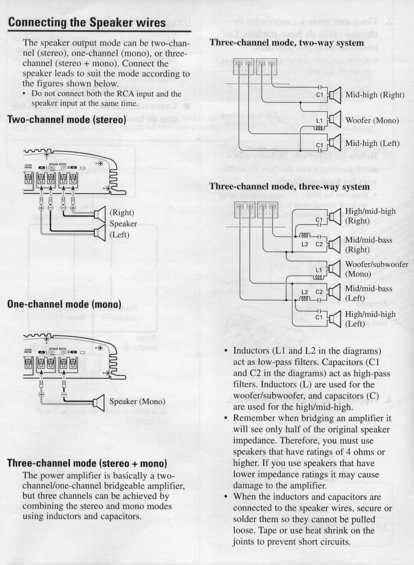


Manual page diagramming how to connect speaker wires in stereo, mono, and three-channel modes using inductors and capacitors.
Part of 1992-1995 Ford Taurus Wiring Diagrams
This document is a page from a car audio amplifier instruction manual explaining how to connect speaker wires in different output modes. It covers four configurations: two-channel mode (stereo, with left and right speakers), one-channel mode (mono, with a single speaker), three-channel mode two-way system (mid-high right, woofer mono, mid-high left), and three-channel mode three-way system (high/mid-high left and right, mid/mid-bass left and right, and a woofer/subwoofer mono channel). The three-channel setups are achieved by combining stereo and mono modes on a bridgeable two-channel/one-channel amplifier using passive crossover components: inductors (L1, L2) act as low-pass filters for the woofer/subwoofer, while capacitors (C1, C2) act as high-pass filters for the high/mid-high drivers. The page warns not to connect both RCA input and speaker input simultaneously, and notes that when bridging, the amplifier sees only half the original speaker impedance, so speakers rated 4 ohms or higher must be used to avoid damaging the amplifier. It also advises securing or soldering inductors and capacitors to the speaker wires and using tape or heat shrink to prevent short circuits. Diagrams illustrate each wiring configuration. Useful for anyone building a homemade passive crossover for a bridged amplifier installation.
Is this accurate? Sign in to help verify it.
Frequently asked questions
- What speaker output modes can the amplifier use?
- Two-channel mode (stereo), one-channel mode (mono), or three-channel mode (stereo + mono), with the speaker leads connected according to the figures shown.
- How is three-channel mode achieved on this amplifier?
- The amplifier is basically a two-channel/one-channel bridgeable amplifier; three channels are achieved by combining the stereo and mono modes using inductors and capacitors.
- What do the inductors and capacitors do in the crossover diagrams?
- Inductors (L1 and L2) act as low-pass filters and are used for the woofer/subwoofer; capacitors (C1 and C2) act as high-pass filters and are used for the high/mid-high speakers.
- What speaker impedance should be used when bridging the amplifier?
- When bridging, the amplifier sees only half of the original speaker impedance, so you must use speakers rated 4 ohms or higher; lower impedance ratings may damage the amplifier.
- Can I connect both RCA input and speaker input at the same time?
- No: the document states not to connect both the RCA input and the speaker input at the same time.


No comments yet.