Home/
Registry/
Ford/
Bronco/
1992-1996/
1993 Ford Bronco/
Photo
supermotors.net/registry/media/601705
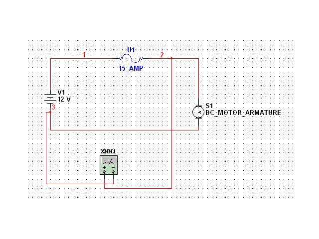
12V DC Motor Circuit Simulation - 15A Fuse & Multimeter Voltage Test Diagram
Reference · 1992-1996 BroncoAll 411 wiring diagrams
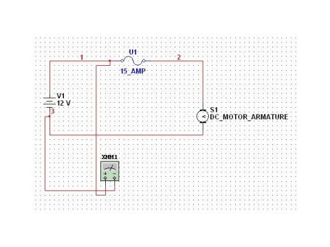
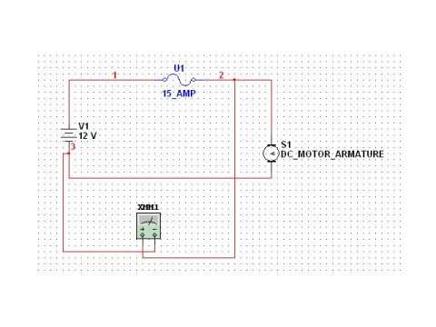
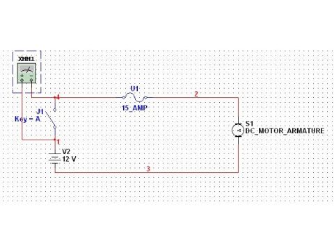
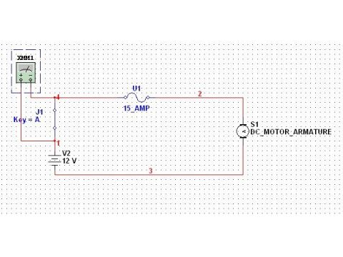
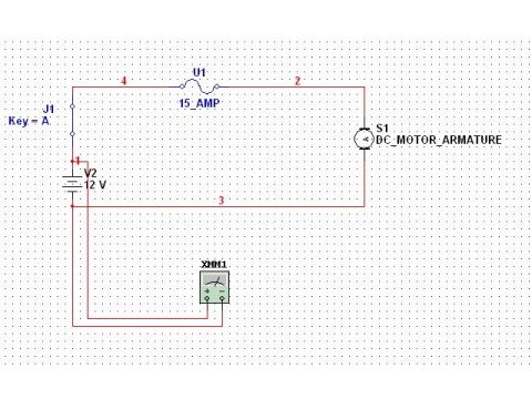
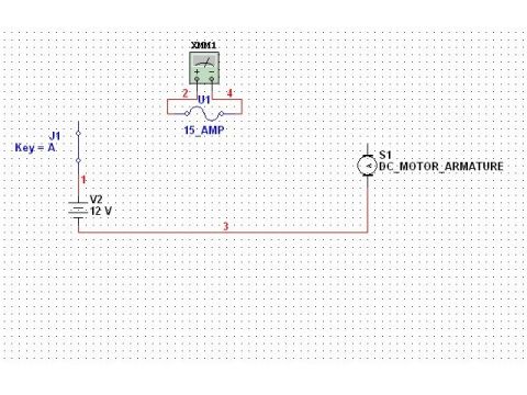
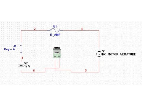








Electrical circuit schematic showing a 15 amp fuse, 12V source, DC motor armature, and multimeter.
Part of 1992-1996 Ford Bronco Wiring Diagrams
This document is a screenshot of a simple simulated electrical circuit drawn in a circuit-simulation program (schematic capture style, e.g., Multisim). The circuit consists of a 12-volt DC source labeled V1, a fuse labeled U1 rated 15_AMP, a DC motor armature labeled S1 (DC_MOTOR_ARMATURE), and a multimeter instrument labeled XMM1 connected into the circuit, apparently to measure voltage or current. Wire nets are numbered 1 (between the battery positive terminal and the fuse), 2 (between the fuse output and the motor), and 3 (on the battery's other terminal). The filename 'TestVLT2.jpg' and companion files in the album (AMP.jpg, FUSE.jpg, SRCVLT.jpg, SWTCH CLSD.jpg, SWTCH OP.jpg, tstvlt1.jpg) suggest this is part of a tutorial series demonstrating basic automotive-style circuit testing: measuring source voltage, amperage, fuse condition, and switch open/closed states with a multimeter. A reader can learn the basic layout of a fused 12V motor circuit and where a meter is placed to test it. It is not a factory Ford wiring diagram and contains no vehicle-specific wire colors, connectors, or part numbers.
Is this accurate? Sign in to help verify it.
Frequently asked questions
- What voltage is the power source in this circuit?
- The source V1 is a 12 V battery/DC supply.
- What is the fuse rating shown in the diagram?
- The fuse U1 is labeled 15_AMP (15 amps).
- What load is connected in the circuit?
- A DC motor armature, labeled S1 (DC_MOTOR_ARMATURE).
- What test instrument is shown in the circuit?
- A multimeter labeled XMM1 is connected into the circuit.
- How are the circuit nodes labeled?
- Wire nets are numbered 1 (battery positive to fuse), 2 (fuse to motor), and 3 (battery negative side).






No comments yet.