1987 Suzuki Samurai Piston Diagram - Hand-Drawn Schematic (Unlabeled)
Reference · 1986-1995 SamuraiAll 18 schematics



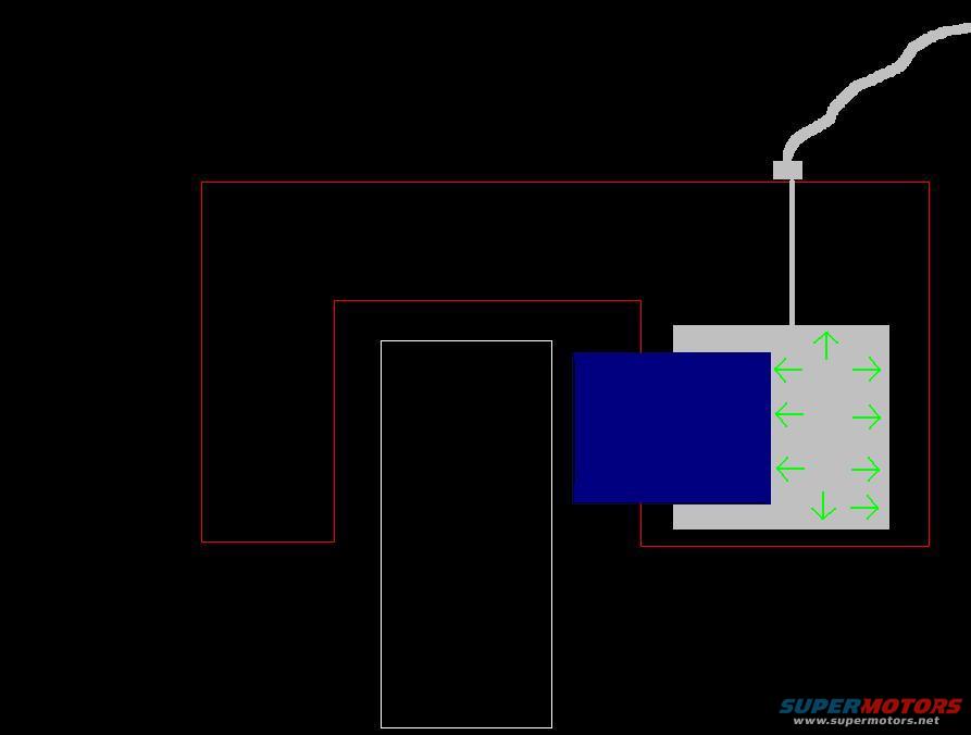
Simple conceptual schematic showing blocks linked by a cable with green expansion arrows on one box.
Part of 1986-1995 Suzuki Samurai Schematics
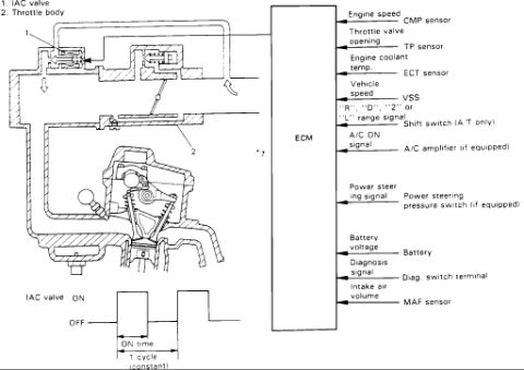
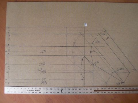
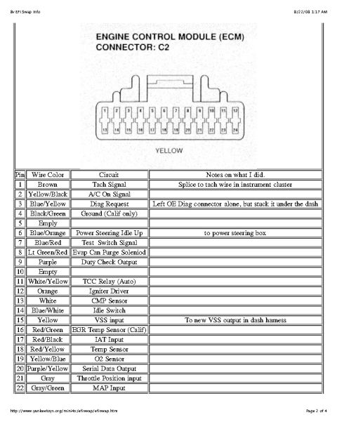
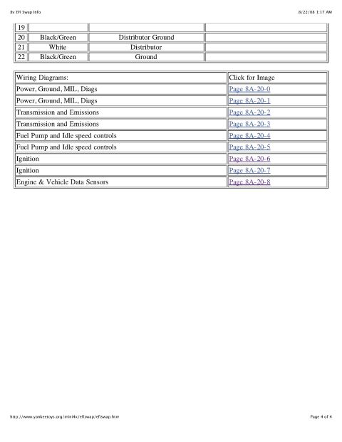
This document is an untitled, unlabeled schematic drawing uploaded as 'pistons.jpg' to a 1987 Suzuki Samurai gallery on SuperMotors.net. It contains no text of any kind. The drawing shows a black background with a large red-outlined boundary and a second, smaller red-outlined boundary inside it, suggesting a cross-section or cavity (possibly an engine block or cylinder area, given the filename). A white-outlined rectangle extends downward from the inner region, and a solid dark blue rectangle sits adjacent to a gray rectangle. The gray rectangle contains green arrows pointing outward in multiple directions (left, right, up, and down), which likely indicate force, pressure, or expansion direction. A gray wavy line resembling a wire or hose runs from the top edge of the drawing down through the red boundary to a small gray square connector attached to the gray rectangle. Because there are no labels, legends, part numbers, torque values, or dimensions, the reader can only infer the general concept, apparently illustrating something (perhaps a piston, sensor, or expanding component) exerting or receiving outward force within a housing. A companion page, pistons-2.JPG, exists in the same album and may provide context.
Is this accurate? Sign in to help verify it.
Frequently asked questions
- Does this diagram include any part numbers or torque specs?
- No. The drawing contains no text at all, no part numbers, torque values, dimensions, or labels.
- What does the diagram actually show?
- It shows only colored shapes: red outlined boundaries, a white rectangle, a blue rectangle, and a gray block with green arrows pointing outward in several directions, connected by a gray wavy line to a small square connector.
- What do the green arrows indicate?
- The document does not say. They point left, right, up, and down from the gray block, visually suggesting outward force, pressure, or expansion, but no legend is provided.
- Does the diagram confirm it applies to a 1987 Suzuki Samurai?
- No. There is no text, year, model, or engine identification anywhere in the drawing.

No comments yet.