Performance Tool Pulley Installer Instructions - Press Pulley onto Shaft

Reference · 1992-1996 BroncoAll 143 service procedures
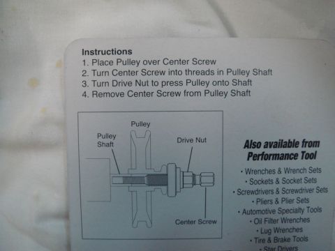

Performance Tool pulley installer instruction card with four numbered steps and a labeled cross-section diagram.
Part of 1992-1996 Ford Bronco Service Procedures
This document is the printed instruction card from a Performance Tool pulley installer kit, photographed lying on a cloth surface. It provides a four-step procedure for installing a pulley onto a shaft using the tool: (1) place the pulley over the center screw, (2) turn the center screw into the threads of the pulley shaft, (3) turn the drive nut to press the pulley onto the shaft, and (4) remove the center screw from the pulley shaft. A labeled cross-section illustration accompanies the instructions, identifying the Pulley, Pulley Shaft, Drive Nut, and Center Screw, and showing how the tool threads into the shaft to draw the pulley into position. The right side of the card lists other product categories available from Performance Tool, including wrenches and wrench sets, sockets and socket sets, screwdrivers and screwdriver sets, pliers and plier sets, automotive specialty tools, oil filter wrenches, lug wrenches, tire and brake tools, and star drivers (the last line is partially cut off). The card is generic tool instructions with no vehicle-specific applicability, part numbers, torque values, or dates. It would typically be used when reinstalling a pressed-on pulley, such as a power steering pump pulley, without hammering or damaging the component.
Is this accurate? Sign in to help verify it.
Frequently asked questions
- How do I use the pulley installer tool?
- Place the pulley over the center screw, turn the center screw into the threads in the pulley shaft, turn the drive nut to press the pulley onto the shaft, then remove the center screw from the pulley shaft.
- What are the parts of the pulley installer shown in the diagram?
- The diagram labels the Pulley, Pulley Shaft, Drive Nut, and Center Screw.
- What actually presses the pulley onto the shaft?
- Turning the Drive Nut presses the pulley onto the shaft while the center screw is threaded into the pulley shaft.
- What should be done after the pulley is installed?
- Remove the Center Screw from the Pulley Shaft (step 4).
- What other products does Performance Tool offer?
- Wrenches & wrench sets, sockets & socket sets, screwdrivers & screwdriver sets, pliers & plier sets, automotive specialty tools, oil filter wrenches, lug wrenches, tire & brake tools, and star drivers.


No comments yet.