Home/
Registry/
Ford/
Taurus/
1996-1999/
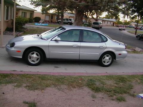
1997 Ford Taurus/
Photo
supermotors.net/registry/media/647862
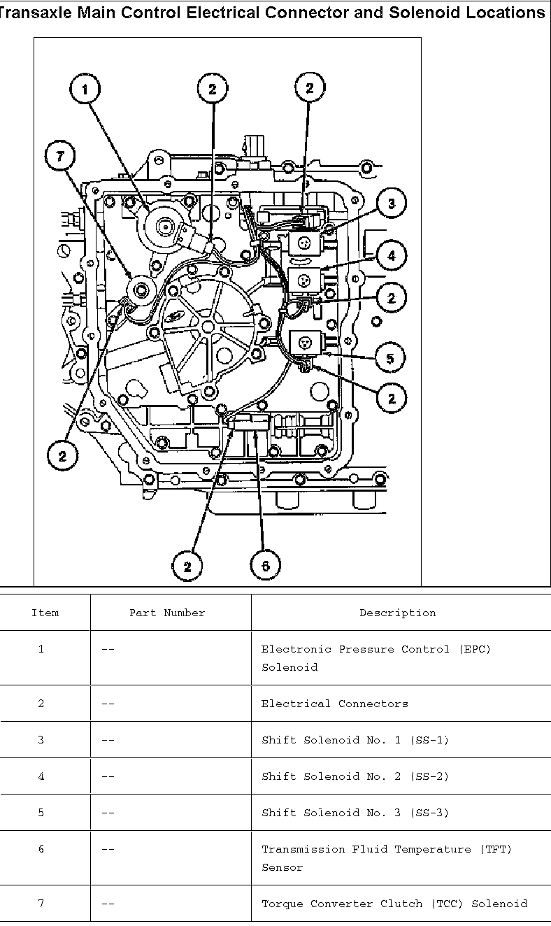
Ford AX4N Transaxle Solenoid & Connector Locations Diagram - Taurus
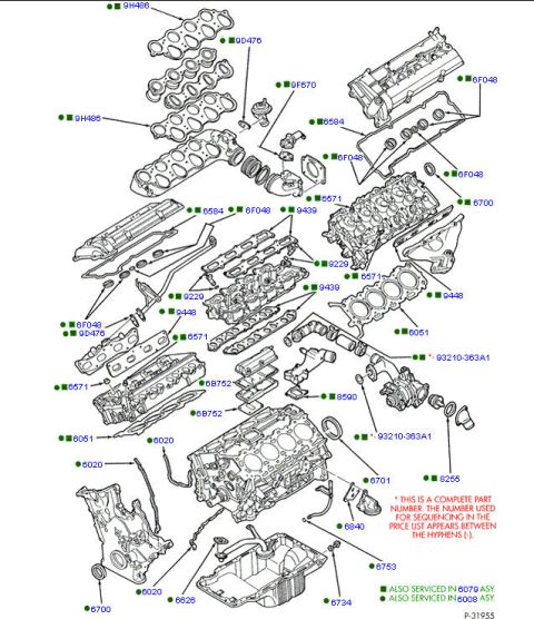
Reference · 1996-1999 TaurusAll 17 exploded parts diagrams
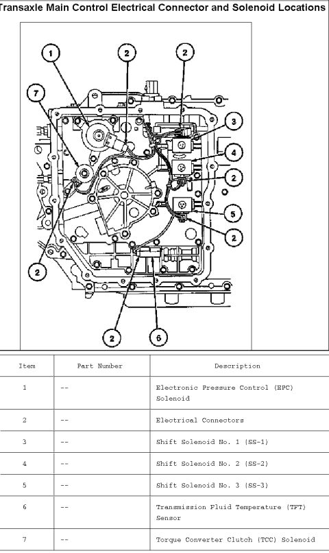
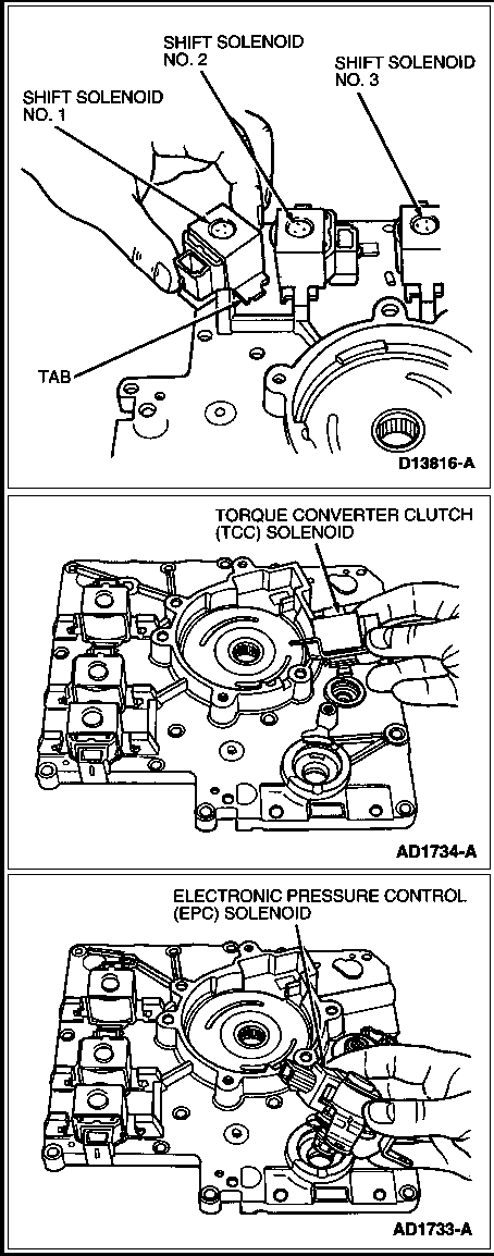


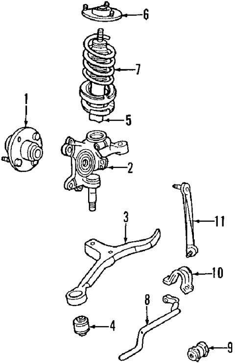
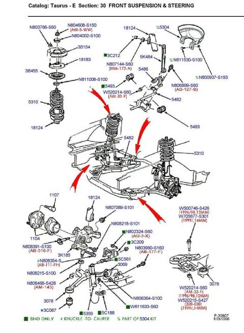
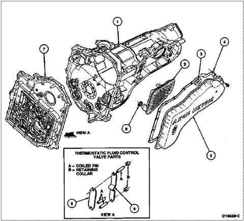


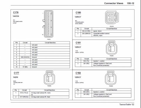

Ford transaxle main control component-location diagram keying EPC solenoid, shift solenoids SS-1/SS-2/SS-3, TFT sensor, TCC solenoid and electrical connectors.
Part of 1996-1999 Ford Taurus Exploded Parts Diagrams
This document is a service-manual style diagram titled "Transaxle Main Control Electrical Connector and Solenoid Locations." It shows a line drawing of an automatic transaxle main control (valve body) area with seven numbered callouts identifying the locations of electrical components. A legend table below the illustration identifies each item: (1) Electronic Pressure Control (EPC) Solenoid, (2) Electrical Connectors (indicated at multiple points on the diagram), (3) Shift Solenoid No. 1 (SS-1), (4) Shift Solenoid No. 2 (SS-2), (5) Shift Solenoid No. 3 (SS-3), (6) Transmission Fluid Temperature (TFT) Sensor, and (7) Torque Converter Clutch (TCC) Solenoid. No part numbers are listed in the table (all shown as "--"). The uploader filed this under a 1997 Ford Taurus with a filename referencing the AX4N transaxle, and companion scans in the album cover AX4N solenoids, AX4N test ports, AX4S ports, and the C168 transaxle connector. A reader can use this diagram to physically locate each solenoid and sensor on the transaxle main control for diagnosis or replacement, such as identifying which shift solenoid corresponds to a diagnostic trouble code or finding the TFT sensor and EPC solenoid positions.
Is this accurate? Sign in to help verify it.
Frequently asked questions
- Where is the Electronic Pressure Control (EPC) solenoid located on the transaxle main control?
- The EPC solenoid is item 1 in the diagram, located at the upper left area of the transaxle main control assembly.
- How many shift solenoids are shown on this transaxle main control?
- Three: Shift Solenoid No. 1 (SS-1, item 3), Shift Solenoid No. 2 (SS-2, item 4), and Shift Solenoid No. 3 (SS-3, item 5), located along the right side of the main control.
- What is item 6 in the diagram?
- Item 6 is the Transmission Fluid Temperature (TFT) Sensor, located near the bottom center of the main control.
- Where is the Torque Converter Clutch (TCC) solenoid?
- The TCC solenoid is item 7, shown at the upper left of the main control near the EPC solenoid.
- Does the document list part numbers for the solenoids?
- No. The Part Number column in the legend table shows '--' for all seven items.




No comments yet.