Home/
Registry/
Ford/
Mustang/
2005-2014/
“SHELBY GT500”/
Photo
supermotors.net/registry/media/655675
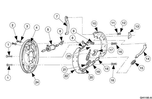
Ford Rear Drum Brake Exploded Parts Diagram GH1195-A - Shoes, Springs, Adjuster
Reference · 2005-2014 MustangAll 44 exploded parts diagrams
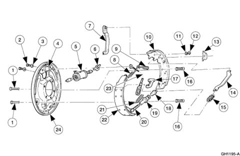
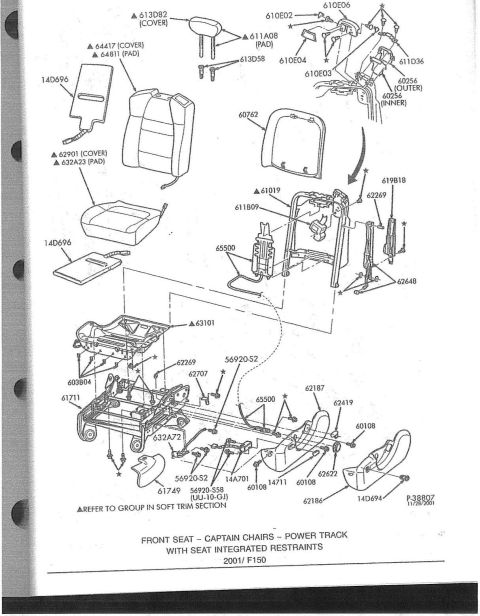
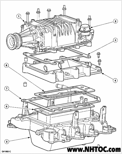
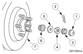









Exploded parts breakdown of a drum brake assembly showing backing plate, shoes, springs and hardware with numbered callouts.
Part of 2005-2014 Ford Mustang Exploded Parts Diagrams
This document is an exploded-view parts diagram of a rear drum brake assembly, identified only by the illustration number GH1195-A in the lower right corner. It shows the backing plate, wheel cylinder, brake shoes (leading and trailing), parking brake lever and strut, adjuster mechanism, return and hold-down springs, retaining clips, and mounting bolts, all separated along assembly axes with numbered callout balloons (1 through 24, with numbers 1 and 16 appearing twice for duplicate parts). No textual legend, parts list, part numbers, torque specifications, or vehicle applicability information appears on the page, the callout numbers presumably reference a legend on another page of the source manual. A reader can use the diagram to understand how the rear drum brake components fit together and in what order they assemble onto the backing plate, including the routing of the parking brake actuating lever and cable, spring placement, and adjuster location. It was uploaded to a 2007 Ford Mustang gallery, but the album contains predominantly Ford F-150/truck reference documents, so applicability should be verified against the accompanying legend page.
Is this accurate? Sign in to help verify it.
Frequently asked questions
- What does this diagram show?
- An exploded view of a rear drum brake assembly, including the backing plate, wheel cylinder, brake shoes, springs, adjuster hardware, and parking brake lever, with numbered callouts 1 through 24.
- Does the diagram include a parts list or part numbers?
- No. Only numbered callout balloons (1-24) and the illustration ID GH1195-A are shown; there is no legend, part numbers, or torque specs on this page.
- What is the illustration reference number on this diagram?
- GH1195-A, printed in the lower right corner.
- How many numbered components are identified in the diagram?
- Callouts run from 1 to 24, with numbers 1 and 16 each appearing twice for duplicated parts, indicating 24 distinct component types.






No comments yet.