Home/
Registry/
Ford/
Mustang/
2005-2014/
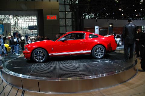
“SHELBY GT500”/
Photo
supermotors.net/registry/media/655653
Ford Supercharger Exploded Diagram - Blower, Gaskets & Lower Intake (GV1565-C)

Reference · 2005-2014 MustangAll 44 exploded parts diagrams
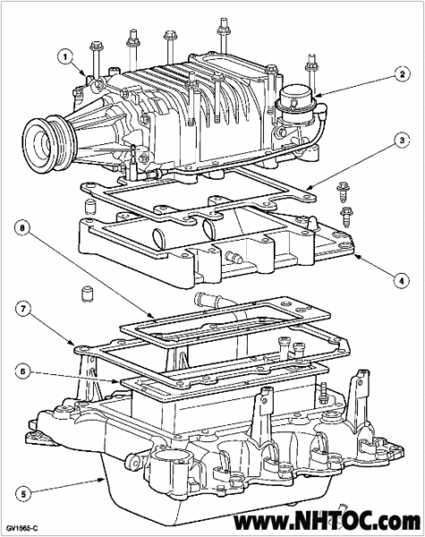
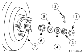
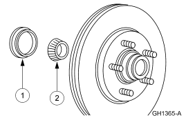
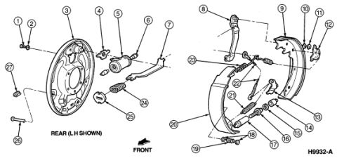
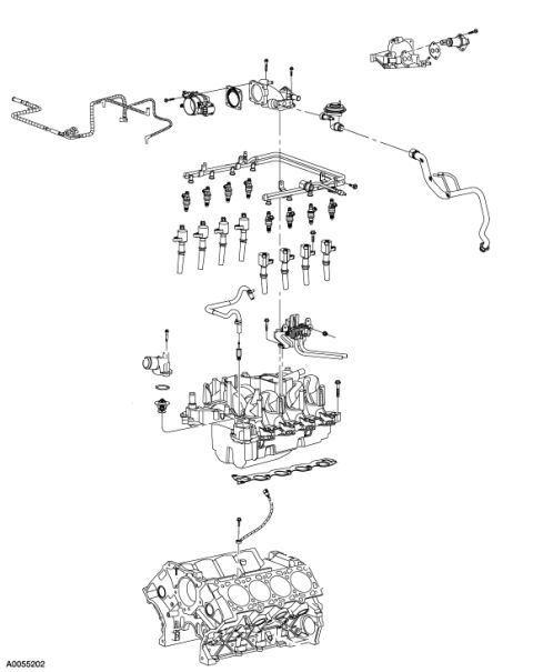
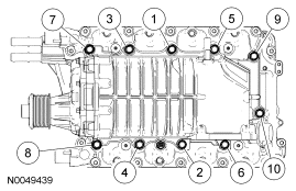
Exploded parts breakdown of a supercharger and intake manifold assembly showing gaskets, bolts and seals with numbered callouts.
Part of 2005-2014 Ford Mustang Exploded Parts Diagrams
This document is an exploded parts diagram (figure ID GV1565-C) showing the disassembly/assembly relationship of a supercharger (blower) and its related intake components. The illustration depicts, from top to bottom: the supercharger assembly with its front drive snout and pulley, mounting studs and bolts, a bypass/actuator component on the right side (callout 2), a gasket (callout 3), an adapter or spacer plate (callout 4), additional gaskets (callouts 8, 7, and 6), and the lower intake manifold assembly (callout 5). Eight numbered callouts identify the major parts, but no accompanying legend, part numbers, or torque specifications appear on this page, the numbers would correspond to a parts list on another page of the source manual. The page carries the watermark www.NHTOC.com and the figure identifier GV1565-C. A reader can learn the stacking order of the supercharger, spacer plate, gaskets, and lower intake manifold, and the general locations of fasteners, which is useful when removing or reinstalling the supercharger assembly.
Is this accurate? Sign in to help verify it.
Frequently asked questions
- What does this diagram show?
- An exploded view of a supercharger (blower) assembly, showing the stacking order of the supercharger, a gasket, an adapter/spacer plate, additional gaskets, and the lower intake manifold, with eight numbered callouts.
- How many gaskets are shown between the supercharger and the lower intake manifold?
- The diagram shows a gasket (callout 3) between the supercharger and the spacer plate, plus additional gaskets (callouts 8, 7, and 6) between the plate and the lower intake manifold.
- Does the diagram include part numbers or torque specs?
- No. It shows only numbered callouts (1-8) and the figure ID GV1565-C; no legend, part numbers, or torque values are printed on this page.
- What is the figure identification number on this diagram?
- GV1565-C.
No comments yet.