Home/
Registry/
Ford/
Mustang/
2005-2014/
“SHELBY GT500”/
Photo
supermotors.net/registry/media/655652
Ford Front Wheel Hub & Bearing Exploded Diagram (GH1364-A) - Outer Bearings

Reference · 2005-2014 MustangAll 44 exploded parts diagrams
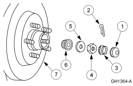
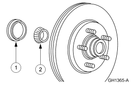
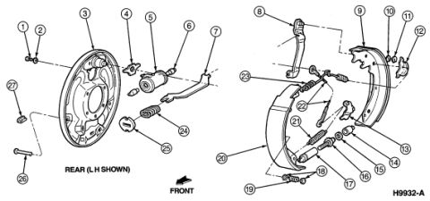
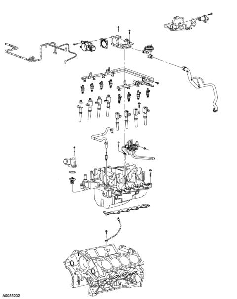
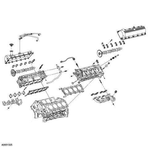









Exploded parts breakdown of a front hub assembly showing bearings, thrust washer, spindle nut and cotter pin with numbered callouts.
Part of 2005-2014 Ford Mustang Exploded Parts Diagrams
This document is a Ford service-manual style exploded parts illustration (figure ID GH1364-A) showing the disassembly sequence of a front wheel hub and bearing assembly. The drawing depicts a hub and disc brake rotor assembly with wheel studs (callout 7) at the left, with components exploding outward to the right: an inner bearing cone (6), a washer (5), a retaining nut (4), an outer wheel bearing (3), a cotter pin (2), and an outermost dust/grease cap (1). The illustration contains no textual legend, part numbers, torque specifications, or vehicle applicability statements, only the numbered callouts and the figure identifier. A reader can learn the order and relative position of the serviceable components of a non-driven, serviceable (tapered-bearing style) front hub: which parts must be removed (cap, cotter pin, nut, washer, outer bearing) to pull the hub/rotor off the spindle. Because the legend text is not included in this scan, the exact Ford part names for each callout must be obtained from the accompanying service manual page. The file was uploaded to a 2007 Ford Mustang gallery, but nothing in the image itself identifies the vehicle.
Is this accurate? Sign in to help verify it.
Frequently asked questions
- What does this diagram show?
- It is an exploded view of a front wheel hub/rotor assembly with seven numbered callouts, showing the order of components: hub and rotor with studs (7), inner bearing (6), washer (5), nut (4), outer bearing (3), cotter pin (2), and dust/grease cap (1).
- What is the figure identification number on this illustration?
- The figure ID printed in the lower right corner is GH1364-A.
- Does the diagram list part numbers or torque specs?
- No. The image contains only the numbered callouts 1-7 and the figure ID GH1364-A; there is no legend, part numbers, or torque values visible.
- In what order do the parts come off the hub according to the diagram?
- Reading from the outside inward: the cap (1), cotter pin (2), outer bearing/retainer (3), nut (4), washer (5), and inner bearing (6) are removed before the hub and rotor assembly (7).






No comments yet.