Home/
Registry/
Ford/
Mustang/
2005-2014/
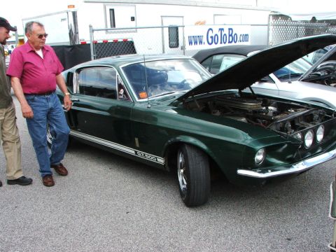
“SHELBY GT500”/
Photo
supermotors.net/registry/media/655651
Ford Front Rotor Hub Bearing & Seal Exploded Diagram GH1365-A

Reference · 2005-2014 MustangAll 44 exploded parts diagrams
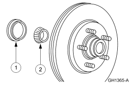
Exploded parts breakdown of a front wheel hub and brake rotor with numbered inner and outer wheel bearings.
Part of 2005-2014 Ford Mustang Exploded Parts Diagrams
This document is a single exploded-parts line drawing (figure ID GH1365-A) showing a front disc brake rotor and hub assembly with five wheel studs, along with two components removed and exploded outward from the hub. Callout 1 identifies a ring-shaped component, which appears to be a grease seal or bearing cup/race, and callout 2 identifies a tapered roller bearing. The drawing contains no accompanying legend, table, part numbers, torque specifications, or vehicle applicability text, only the two numbered callouts and the figure identifier in the lower-right corner. A reader can learn the relative position and orientation of the inner bearing components as they seat inside the rotor/hub: the bearing (callout 2) installs into the hub first, followed by the seal/race (callout 1) on the inboard side. Because the image carries no captions, the exact part names must be inferred from a companion service-manual text page that would normally reference these callout numbers. The document was uploaded to a 2007 Ford Mustang gallery, but nothing in the drawing itself confirms or denies that application; the surrounding album files suggest Ford truck (F-150) service-manual illustrations.
Is this accurate? Sign in to help verify it.
Frequently asked questions
- What components are shown in this diagram?
- The diagram shows a front disc brake rotor/hub assembly with five wheel studs and two exploded components: callout 1 (a ring-shaped seal or bearing race) and callout 2 (a tapered roller bearing).
- Where do the bearing and seal install?
- Per the exploded view, the tapered roller bearing (callout 2) seats into the inboard side of the rotor/hub, with the ring-shaped seal/race (callout 1) positioned outboard of it on the same inboard face.
- Does the diagram list part numbers or torque specs?
- No. The only text visible is the two callout numbers (1 and 2) and the figure identifier GH1365-A; there is no legend, part number, or torque information.
- What is the figure identification number of this illustration?
- The figure ID printed in the lower-right corner is GH1365-A.
No comments yet.