Home/
Registry/
Ford/
Mustang/
2005-2014/
“SHELBY GT500”/
Photo
supermotors.net/registry/media/661880
2001 Ford F-150 5.4L Fuel Pump Wiring Diagram - Relay, Inertia Switch, PCM
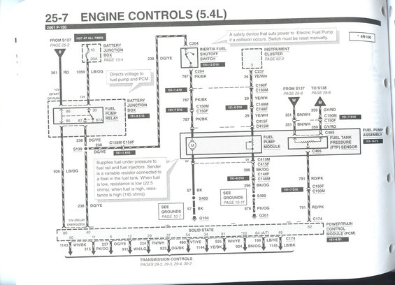
Factory wiring diagram for 2001 Ford P-150 5.4L engine controls showing fuel pump, PCM and connector circuits with color codes.
This is page 25-7 of a Ford factory wiring diagram manual, covering Engine Controls (5.4L) for the 2001 Ford F-150 — specifically the fuel pump circuit. It shows power flow from a 20A fuse (position 10) in the Battery Junction Box through the Fuel Pump Relay (pins 30, 85, 86, 87, 87A), then via circuit 238 DG/YE to the Inertia Fuel Shutoff Switch and onward as circuit 787 PK/BK to the Fuel Pump Module. The diagram includes the fuel level sender circuit (29 YE/WH to the Instrument Cluster), the Fuel Tank Pressure (FTP) Sensor wiring (351 BN/WH and 359 GY/RD, with 791 RD/PK signal to PCM pin 62), and grounds G104 and G201 through splice S400. Callouts explain that the inertia switch cuts fuel pump power in a collision and must be reset manually, and that the fuel sender is a variable resistor (22.5 ohms low fuel, 145 ohms full). Connector identifiers (C204, C237, C148, C150, C158, C160, C174, C415, C465) and cross-references to other manual pages (13-4, 25-2, 25-6, 62-2, 10-7, 10-11, transmission pages 29-2 through 30-2) are included, along with PCM pin numbers and wire colors. A note marks 4R100 transmission applicability.
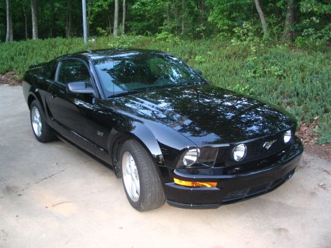
This document covers 2001, which may differ from this 2007 Ford Mustang.
Is this accurate? Sign in to help verify it.
Frequently asked questions
- What fuse powers the fuel pump relay on the 2001 F-150 5.4L?
- Fuse 10, a 20A fuse in the Battery Junction Box (see page 13-4), on a circuit hot at all times, feeding the fuel pump relay via wire 1059 LB/OG.
- What wire color feeds the fuel pump on a 2001 F-150 5.4L?
- Circuit 238 DG/YE runs from the fuel pump relay to the Inertia Fuel Shutoff Switch (connector C204), then circuit 787 PK/BK continues through C150M/C150F to the fuel pump module.
- What does the inertia fuel shutoff switch do?
- It is a safety device that cuts power to the electric fuel pump if a collision occurs. The switch must be reset manually.
- What are the fuel level sender resistance values?
- The sender is a variable resistor connected to a float in the fuel tank: resistance is low (22.5 ohms) when fuel is low and high (145 ohms) when fuel is high.
- Which PCM pin receives the fuel tank pressure sensor signal?
- The FTP sensor signal travels on circuit 791 RD/PK through connectors C150F/C150M and C174 to PCM pin 62.
Comments
More from this build













No comments yet.